D.c. electrical connections – Winco PSS40LS/C User Manual
Page 11
60706-188
Page 9
7263-00
B - Generator Circuit Breaker, This circuit breaker provides
overload protection for the generator. Your power feeds from the
transfer switch will connect to the bottom lugs on the circuit
breaker. The generator power feeds have already been wired
into the upper lugs.
The table below gives you the circuit breaker size, lug wire sizes
and torque specification. (see the actual breaker for additional
information and restrictions)
kW
Voltage PH
Amp
Wire Capability
Lug Torque
40
120/240
1
175
#4 AWG - 300 MCM 250 in lbs
40
120/208
3
150
#4 AWG - 300 MCM 250 in lbs
40
120/240
3
125
#4 AWG - 300 MCM 250 in lbs
40
277/480
3
60
#14 - #1/0 AWG
80 in lbs
27
120/240
1
110
#4 AWG - 300 MCM 250 in lbs
27
120/208
3
90
#12 AWG -2/0 AWG 50 in lbs
27
120/240
3
80
#12 AWG -2/0 AWG 50 in lbs
27
277/480
3
40
#14 - #1/0 AWG
80 in lbs
Minimum Conductor Sizes between the Generator and the ATS.
Based on wire type and temperature rating. Wire has been
derated for 40
o
C ambient temperatures.
CU Conductor
AL Conductor
C/B
Wire Temperature Rating
kW Voltage PH Amp 75
0
C
90
0
C
75
0
C
90
0
C
40 120/240 1
175
3/0 AWG 2/0 AWG 250 MCM 4/0 AWG
40 120/208 3
150
2/0 AWG 1/0 AWG 3/0 AWG 2/0 AWG
40 120/240 3
125
1/0 AWG #1 AWG
3/0 AWG 2/0 AWG
40 277/480 3
60
#4 AWG #6 AWG
#3 AWG #4 AWG
27 120/240 1
110
#1 AWG #2 AWG
1/0 AWG #1 AWG
27 120/208 3
90
#2 AWG #3 AWG
1/0 AWG #2 AWG
27 120/240 3
80
#3 AWG #4 AWG
#1 AWG #2 AWG
27 277/480 3
40
#6 AWG #6 AWG
#6 AWG #6 AWG
For additional information on wire sizing refer to table 310-16 of
the National Electrical Code ANSI/NFPA 70.
C - Ground Lug, These ground lugs are bonded to ground and
are provided for you to connect your ground wire from the transfer
switch to. The lugs on the 40 kW will handle wire sizes #6 AWG
to 250 MCM and should be torqued to 250 in. lbs. The lugs on the
27 kW will accommodate #6 AWG to 250 MCM and should be
torqued to 250 in. lbs.
*************
***** WARNING *****
*************
A main line circuit breaker has been provided inside the genera-
tor housing. During all wiring installations make sure the breaker
is in the off position and the generator operation switch is in the
off position.
*************
***** WARNING *****
*************
EQUIPMENT DAMAGE - When installing a Three Phase 240 volt
system be sure you know which lead is the high voltage "wild" leg
(208Volt line to neutral). The generator normally carries the high
voltage on the G2 lead.
The load current carrying wires (L) and (T) must be sized to
handle the maximum load current without excessive voltage drop.
By code, the wire must be heavy enough to handle the full current
rating of the main line circuit-breaker (or fuse) in the entrance (or
sub-panel) protecting the contactor switch.
All wires should be installed in rigid or flexible conduit. (Knock-
outs are provided in the control box).
See the manual shipped with the Automatic Transfer Switch for
connection locations in the switch. Connections in each switch
will vary depending on the type of switch and the manufacturer.
GROUNDING
A grounding lug has been provided on the engine generator set
and the generator set must be properly grounded to good earth
ground. Generally a 6 foot copper rod driven into the earth will
provide a proper earth ground.
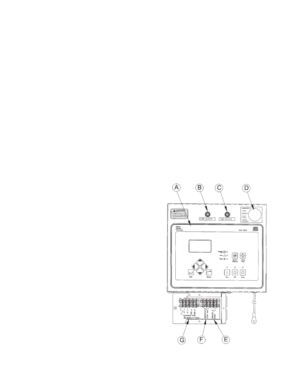
D.C. ELECTRICAL
CONNECTIONS
All DC connections are completed in the small box just below the
engine control cabinet. In addition there are two small fuses
mounted on the top of the engine control cabinet that protect both
the engine control and all the other DC connections. See the
display below for additional information.