Winco PSS40LS/B User Manual
Page 9
60706-148
Page 7
1108-20
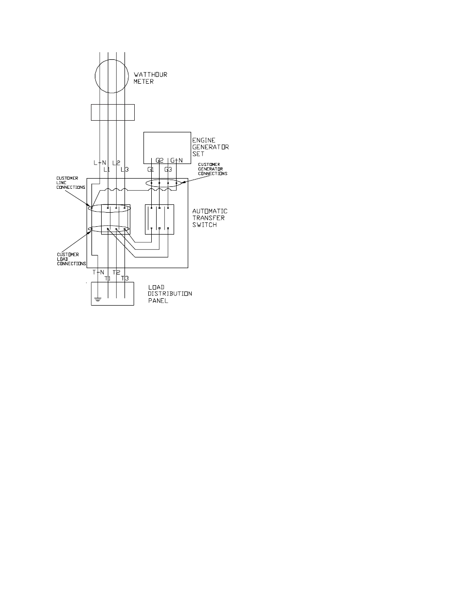
Three phase unit shown, for single phase
wiring disregard L-2, T-2, G-2.
lower lugs on the line side contactor. Jumper leads have already
been installed between the lower lugs on the line side and the
lower lugs on the generator side contactors. The T-N connection
will be made on the standoff just to the left of the contactor.
An equipment grounding lug is provided just above the
T-N connection for your use in grounding the transfer switch.
All the neutral leads (G-N, L-N and T-N) must be carried through
the A.T.S. These leads are all bonded together within the A.T.S.
and are bonded to GROUND at one common point. If your
system requires an isolated neutral, this neutral to ground bond
can be isolated by removing the copper strap located between
the LINE terminal L-N and the ground lug in the panel. This
action, along with lifting the Neutral to Ground bond in the
generator connection cabinet, will effectively change this unit to a
fully isolated neutral system.
The generator output leads in the generator connection box
follow the same marking pattern. i.e. G1, G-N and G3 on the
single phase and G1, G2, G3 and G-N on the three phase units.
*************
***** WARNING *****
*************
EQUIPMENT DAMAGE - When installing a Three Phase 240 volt
system be sure you know which lead is the high voltage "wild" leg
(208Volt line to neutral). The generator normally carries the high
voltage on the G3 lead.
FIGURE 5
The load current carrying wires (L) and (T) must be sized to
handle the maximum load current without excessive voltage drop.
By code, the wire must be heavy enough to handle the full current
rating of the main line circuit-breaker (or fuse) in the entrance (or
sub-panel) protecting the contactor switch.
A fused disconnect (circuit breaker or fuses) must be
installed between the engine generator and the A.T.S. panel.
Failure to install a proper fused disconnect will void any
warranty on the generator end. All wiring from the engine-
generator to the transfer switch must be of sufficient size to
handle the appropriate fused disconnect amperage.
All wires should be installed in rigid or flexible conduit. (Knock-
outs are provided in the control box).
Because of the many different types of service, feeder, and
distribution equipment, no specific wiring instructions can be
provided. It is recommended that only copper wire be used. In
all cases it is essential that while the load is connected to the
generator, there can be absolutely no feedback from the
generator to the power line or the power line to the generator.
When properly installed, the normal A.T.S. Control and safety
systems will eliminate all paths for feedback.
To wire the automatic transfer switch into the existing wiring, first
determine which circuits will be on the emergency load circuit. If
the entire load is to be transferred, the transfer switch can be
wired in directly after the watt-hour meter and the service
entrance, providing the service entrance ampere rating is within
the transfer switch’s rated capability.
If only specific circuits are to be powered under emergency power
failure conditions, an additional distribution panel designated
“emergency distribution panel” must be installed.
All selected emergency circuits are removed from main distribu-
tion panels and installed in the emergency distribution panel. The
A.T.S. is then installed between the main panel and the emer-
gency distribution panel. Suggested circuits: freezer, refrigerator,
furnace, emergency lights, sump pump, emergency outlet circuits,
etc. Total running load must not exceed generator rating.
D.C. ELECTRICAL INTERCONNECTION
PSS27LS and PSS40LS
Two control wires are required between the A.T.S. panel and the
generator control terminal box. Depending on the distance, 14 to
16 gauge stranded wire should be used. These wires will be
labeled S1 and S23.
*************
***** WARNING *****
*************
Be sure both the mode switch on the Engine Generator and the
mode switch in the Automatic Transfer Switch are in the "OFF"
postition before you make any DC interconnections.
Service
Entrance