Winco PSS40LS/B User Manual
Page 6
Page 4
1108-20
60706-148
ENGINE GENERATOR SET MOUNTING
The unit’s main frame should be bolted solidly to a 4 to 6 inch
thick cement pad. The engine-generator is mounted on a sub-
frame which is attached with special shock mounts to the main
frame. This allows the engine-generator free movement without
affecting the control panel which is mounted on the main frame.
Do not shock mount the main frame. Engine vibration will be
transmitted to the control panel causing erroneous start/stop
cycles and premature control failure.
The unit should be mounted to allow for ample working room
around it. A general rule to follow is three (3) feet clearance on
all sides.
FUEL INSTALLATION
The fuel supply should be as close as possible to the engine.
This will reduce the installation cost of fuel runs. The informa-
tion in this manual is offered to assist you in providing the proper
fuel for your engine. However, this information is only provided to
inform you of the engine’s requirements and assist in making you
aware of the decisions you must make. In no case should the
instructions or information provided be interpreted to conflict with
any local, state or national codes. If in doubt, always consult your
local fire marshal or gas supplier.
*************
***** WARNING ****
*************
FIRE HAZARD - All fuel runs should be installed by a licensed
fuel supplier.
Connect the fuel supply to the inlet of the fuel solenoid (see table
for recommended line size). The pressure at the secondary
demand regulator must be four to six ounces psi (per square
inch) or 7 to 11 inches W.C. (Water column) for vapor withdrawal
units. On units equipped with liquid withdrawal fuel systems full
tank pressure is plumbed to the fuel lock strainer mounted on
the generator rails. The fuel converter mounted on the unit will
handle both vaporization of the fuel and pressure reduction.
INSTALLING THE FUEL LINE
** NOTICE **
The engine generator sets are properly adjusted before they
leave the factory for a specific fuel, either NG (natural gas), LP
(liquid propane vapor) or LPG (liquid withdrawl propane). This
fuel type is noted in your model number. If it becomes necessary
to change the fuel type in the field see information on page 10.
Line Size (vapor system)
Unit location will determine the size of fuel line that is required to
supply the engine with a constant fuel pressure. Refer to the
tables below for fuel line size, fuel consumption and recom-
mended tank size. For distances of 25 feet and over, a two
regulator fuel system is recommended. This is accomplished by
installing a primary regulator at the tank which will reduce the
tank pressure down to 10 to 15 lbs. A secondary regulator is
installed to further reduce the fuel pressure to the required six (6)
oz operating pressure. This secondary regulator must be at least
10 feet from the engine generator set. Any closer installation will
require a larger line be installed to provide a fuel reservoir. If this
is not done, the demand regulator on the unit and the pressure
regulator in the fuel line will interfere with each other. When this
two (2) stage regulator system is used, a fuel line size of 3/4 to 1
inch is generally adequate for distances up to 300 feet from the
primary to the secondary regulator. (Consult your local fuel
supplier for your exact requirements). The appropriate line size
from the table below is then installed from the secondary regula-
tor to the generator set.
*************
***** WARNING ****
*************
PERSONAL DANGER - Do not use galvanized pipe in fuel line
runs. The galvanized coating can become eroded and flake off,
causing possible obstructions in the regulator or fuel valve. The
results could range from inoperative engine start to hazardous
fuel leaks.
Size of pipe normally required for generators operating on
NATURAL/LP gas.
up to 25 feet* over 25 feet*
PSS27LS
1" pipe not recommended
PSS40LS
1" pipe use a two regulator system
* Allow an additional 3 feet for each standard elbow.
Do not use ‘street ells’ (restrictive).
**** CAUTION ****
EQUIPMENT DAMAGE - Be careful when sealing gas line joints.
Excessive sealing compound can be drawn into the solenoid,
regulator or carburetor causing an engine malfunction.
FUEL PRESSURE (vapor system)
Correct fuel pressure cannot be stressed enough. The most
common cause for inoperative systems is an inadequate or
incorrect fuel pressure. Performance of the engine is in direct
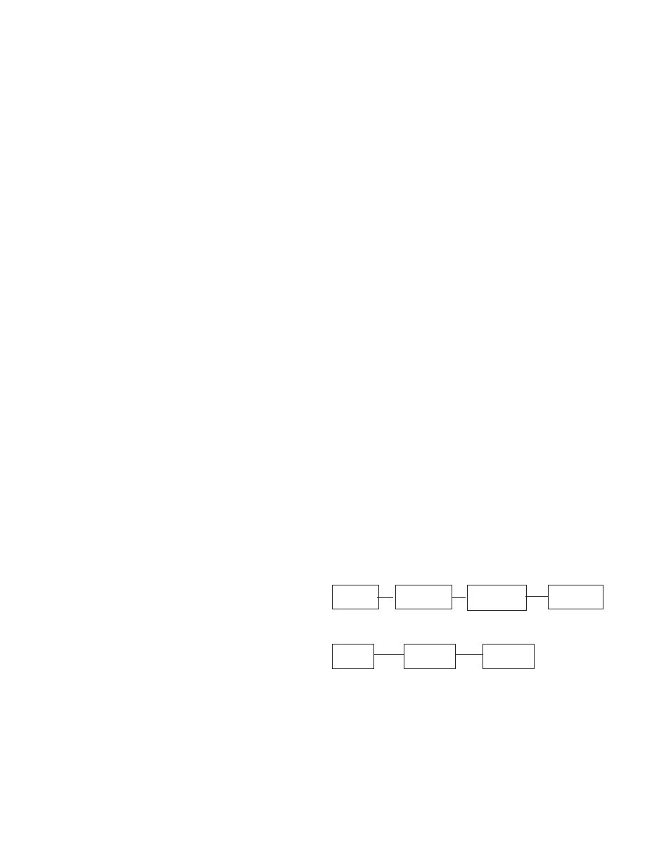
relation to the correctness of the fuel system. Shown below is a
block diagram of a typical L.P. or N.G. Installation.
Supply
Primary
Secondary
Generator
Tank
Regulator
Regulator
Set
1 2
3
4
TWO (2) REGULATOR FUEL SYSTEM
Supply
Primary
Generator
Tank
Regulator
Set
1
2
3
SINGLE REGULATOR FUEL SYSTEM
Reference numbers 1 through 3 in the block diagrams above
are fuel lines supplied by customer.
Reference number 4 is the engine generator set.