Winco PSS20000/E User Manual
Page 11
PAGE 9
and G3-B are both connected to the G3 lead going to the
A.T.S.) The engine control leads are currently connected
to some of the generator leads. These leads must
remain with the generator leads they are connected to.
The neutral lead (GN-A & GN-B) are shipped bonded to
the ground lug. If your local code requires the generator
to be wired with an isolated neutral, remove this neutral
to ground bond. This will require you to run four AC leads
from the generator to the A.T.S. as you will need to run
both a neutral and a ground lead. All wires must be sized
to handle 83 amps minimum, the type of wire you use
will determine the gauge required. Consult your local
wire supplier for proper gauge and type for your area.
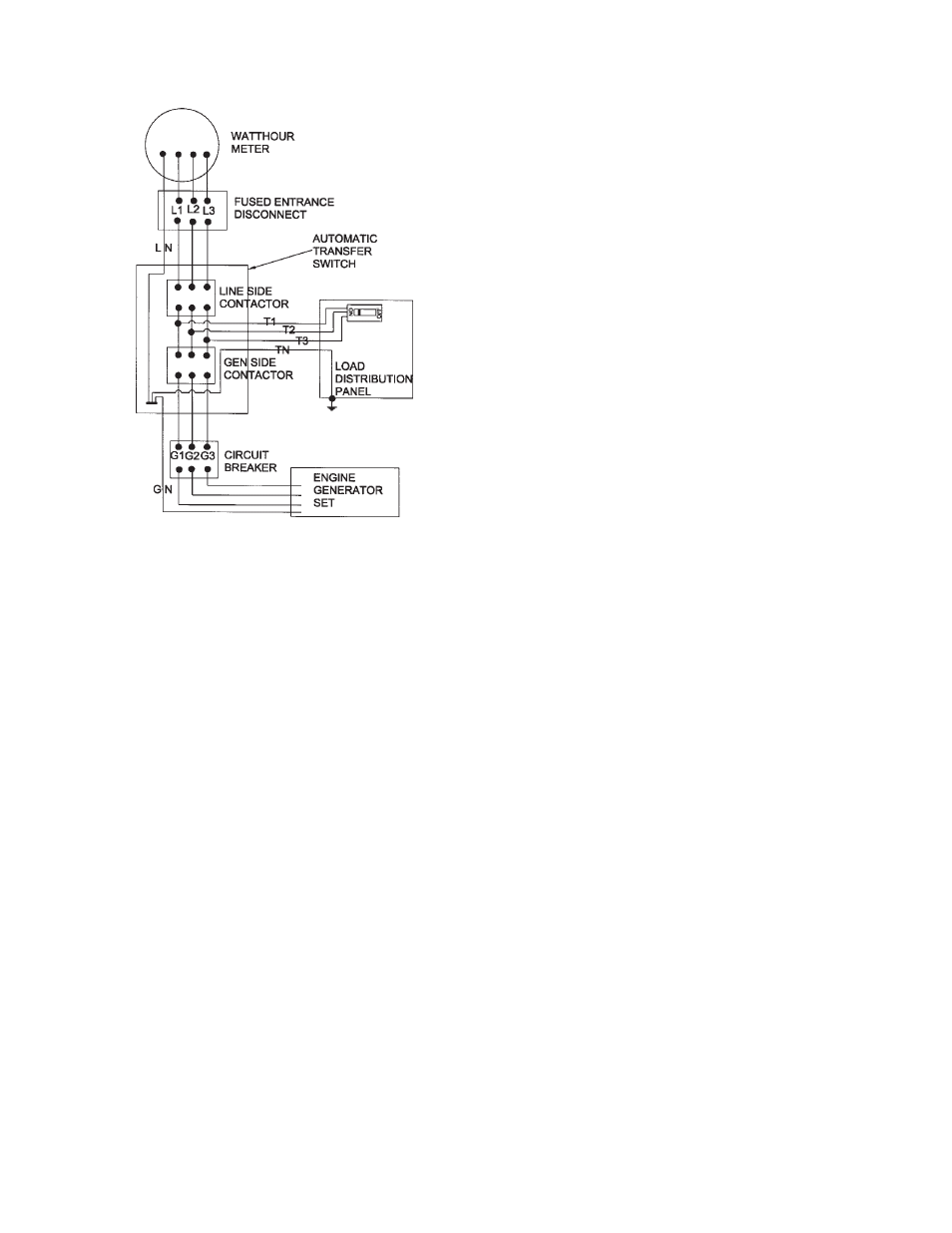
A.T.S. Connections
The standby generator terminals in the A.T.S are
marked “GENERATOR - G1, G-N, G3”. The “hot” leads
G1 and G3 from the generator are wired to the generator
side contactor, terminals G1 and G3. The G-N connec-
tion will be made on the stand-off in the bottom of the ATS
The line terminals in the A.T.S. are marked “LINE - L1,
L-N, L3”. The “hot” load leads L1 and L3 are wired line
side contactor, terminals L1 and L3. The L-N connection
will be made on the stand-off in the bottom of the ATS
The load terminals in the A.T.S. are marked “LOAD - T1,
T-N, T3”. The “hot” leads T1 and T3 will wire directly to
the lugs between the two contactors marked “LOAD”.
Copper jumper straps have already been installed
between the upper terminals on the generator contactor
and the lower terminals on the line side contactors. The
T-N connection will be made on the stand-off in the
bottom of the ATS.
PSS20000 Three Phase
(FIGURE 5)
The three phase units are installed the same as the
single phase units above, except a third power lead is
added, (i.e. a G2 from the generator, L2 on the line side
and a T2 on the load side). In the 120/240 volt configura-
tion the G3, L3 and T3 will be the high voltage (wild) leg.
The other difference is a three phase power monitor
has been installed in the A.T.S. to monitor each phase for
low voltage. This three phase monitor is phase rotation
sensitive and comes from the factory set up for A-B-C
phase rotation. If you have trouble getting the A.T.S. to
pick-up the line power on initial installation, try switching
the A and B phase on the monitor. Your rotation may be
C-B-A. If so, be sure to match the generator rotation to
your current line rotation or your three phase motors will
try to turn backwards.
*************
***** WARNING *****
*************
When installing a Three Phase 240 Volt Delta system be
sure you know which lead is the high voltage leg (208
Volt line to neutral). The generator has the high voltage
lead connected at G3.
INSTALLATION NOTES
The load current carrying wires (L) and (T) must be
sized to handle the maximum load current without
excessive voltage drop. By code, the wire must be heavy
enough to handle the full current rating of the main line
circuit-breaker (or fuse) in the entrance (or sub-panel)
protecting the contactor switch.
All wires should be installed in rigid or flexible conduit.
(Knockouts are provided in the control box)
Because of the many different types of service, feeder,
and distribution equipment, no specific wiring instruc-
tions can be provided. It is, however, recommended that
only copper wire be used. In all cases it is essential that
while the load is connected to the generator, there can be
absolutely no feedback from the generator to the power
line or the power line to the generator. When properly
installed, the normal A.T.S. Control and safety systems
will eliminate all paths for feedback. Check with your
local electrical inspector on applicable local, state and
federal codes.
NOTE:
It is an excellent idea to install a disconnect in the
incoming power line wiring directly in front of the A.T.S.
panel. This will allow you to test the generator under
load. Should you ever have to work on the switch, you
will be able to disconnect the power and work on the
switch cold without having the power company pull your
meter.
FIGURE 5
FULL SYSTEM
THREE PHASE