Winco PSS20000/E User Manual
Page 10
PAGE 8
*************
***** WARNING *****
*************
All wiring must be done by a licensed electrician, and
must conform to the national electrical code and comply
with all state and local codes and regulations. Check with
your electrical inspectors before proceeding!
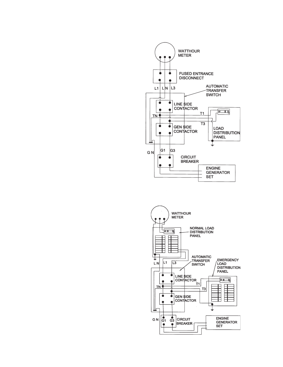
The standard Non-UL Automatic Transfer Switch
shipped with the PSS20000 system has a 230 Amp line
side contactor installed to handle your normal power
needs and a 150 Amp generator side contactor to handle
the emergency generator output. Before installing the
A.T.S. you must first ensure that the 230 Amp line side
contactor will be sufficient to handle your complete
service. See Figure 3. (i.e. the main line breaker must
not be larger than 230 Amps). If you have a larger main
line breaker, you will not be able to transfer the complete
electrical system. In this case it will be necessary to
install a secondary emergency distribution panel. See
Figure 4. NOTE: THE MAXIMUM OUTPUT OF THE
GENERATOR IS 83 AMPS AT 240 VOLTS SINGLE
PHASE, 56 AMPS AT 208 VOLTS AND 48 AMPS AT 240
VOLTS THREE PHASE. You must also take this into
consideration when deciding whether to install an
emergency distribution panel.
*************
***** DANGER *****
*************
Be certain the operation selector switch on the front of the
A.T.S. Control is in the “stop” position and the main power
switch “off”. For your own protection, verify these impor-
tant safety precautions yourself with reliable instruments
before proceeding.
A.C. ELECTRICAL CONNECTIONS
*************
***** WARNING *****
*************
A FUSED DISCONNECT OR CIRCUIT BREAKER
MUST BE INSTALLED BETWEEN THE GENERATOR
AND THE A.T.S. PANEL TO PREVENT OVERLOADING
AND BURNING OUT THE GENERATOR. FAILURE TO
PROVIDE A FUSED DISCONNECT OR CIRCUIT
BREAKER, RATED AT GENERATOR RATING WILL VOID
YOUR WARRANTY IN CASE OF GENERATOR FAIL-
URE.
Single Phase
Generator Connections
To gain access to the customer connections, remove
the panel the warning light and the selector switch are
mounted on, inside the left hand access door. Both AC
and DC connections are made behind this panel. Three
AC power leads are required between the generator and
the A.T.S. The power leads coming into this connection
box from the generator end are run in parallel. (i.e. G1-A
and G1-B are both connected to the G1 lead and G3-A
FIGURE 3
Full System
Single Phase
FIGURE 4
PARTIAL SYSTEM
SINGLE PHASE