Initial start up – Winco PSS8B4W/A User Manual
Page 10
PAGE 8
60706-166
4023-50
All selected emergency circuits are removed from main
distribution panels and reinstalled in the emergency
distribution panel. Suggested circuits: freezer, refrigera-
tor, furnace, emergency lights, sump pump, emergency
outlet circuits, etc. Total running load must not exceed
generator rating.
D.C. ELECTRICAL INTERCONNECTION
*******CAUTION******
Never run the AC and DC wiring in the same conduit.
ASCO 165 UL SWITCH
Your DC connection points in the ASCO 165 UL ATS
are on the terminal block in the upper right hand corner of
the ATS panel. The terminal block (TB7) is numbered 1
through 9. These terminal will accept #22 - #14 stranded
wire. It is recommended that you use #16 for distances
up to 200 feet.
You need to run four (4) wires from the engine generator
set to the transfer switch, see table below.
Wire #
Purpose
Recommended Color
#5
Battery positive
Black
#1
Battery Negative
White
#24
Fuel Solenoid
Red
#22
Start
Orange
You can use any color you want, these color codes are
just a recommendation. The wires terminate on TB7 as
follows:
Wire #
Color
TB7 Terminal
#5
Black
#3
#1
White
#2
#24
Red
#4
#22
Orange
#7
Jumpers will need to be installed as follows:
Wire #
Color
TB7 Terminals
#5
Black
#3 & #5
#5
Black
#5 & #8
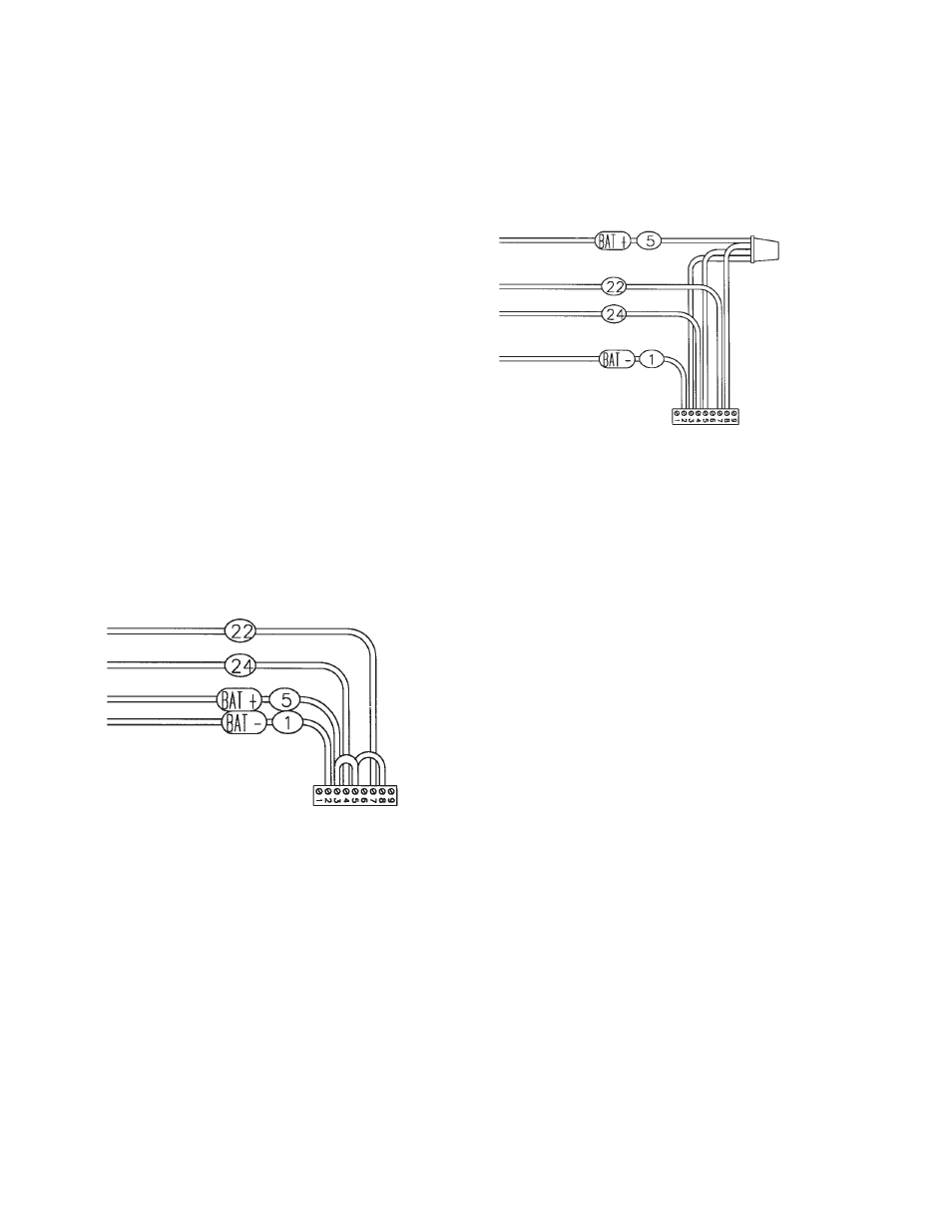
The following is a optional way to interconnect the
Generator and the Transfer Switch. The wires terminate
on TB7 as follows:
Wire #
Color
TB7 Terminal
#1
White
#2
#24
Red
#4
#22
Orange
#7
The following leads are wire nutted together:
Wire #
Color
From
#5
Black
Generator
#5
Black
TB7 #3
#5
Black
TB7 #5
#5
Black
TB7 #8
INITIAL START UP
*************
***** WARNING *****
*************
DO NOT jump start these engine generator sets. Starting
these units on a low battery or jump starting them will
cause damage to the engine control module.
Use the following check list to verify correct installa-
tion before starting the engine:
F
Engine oil.* Check level & fill as required with
proper grade/qty.
F
Unit mounting base properly bolted down.
F
Clearance for service and maintenance on all
sides.
F
Proper fuel line material, and size.
F
All fuel line connections tight.
F
Fuel line protected and a moisture trap installed
(may be required for N.G.).
F
LP/NG pressure O.K. 4-6 Oz. (7-11" WC).
F
Battery connections clean and tight.
F
Battery fully charged.
F
All A.C. and D.C. wiring installed and properly
protected.
* Refer to engine owners manual for proper
levels and type.
After completing the above checklist, the engine-
generator set is ready for the initial start-up test.
PROCEDURE
Engine Generator Set only
Move the right hand toggle switch from stop to the
normal position the alarm light should go out. Next move
the left hand toggle switch from the off to the run position.
You should hear the fuel solenoid engage at this time.
Next lift the toggle switch to the start position and hold.
The starter should engage and the engine will start. As
soon as the engine starts release the toggle switch and it
will return to the run position. If the engine does not start
Optional Connections