Winco PSS12/A User Manual
Page 9
PAGE 7
0306-01
60706-147
(i.e. the main line breaker must not be larger than 110
Amps) If you have a 125, 150 , 200 Amp or larger
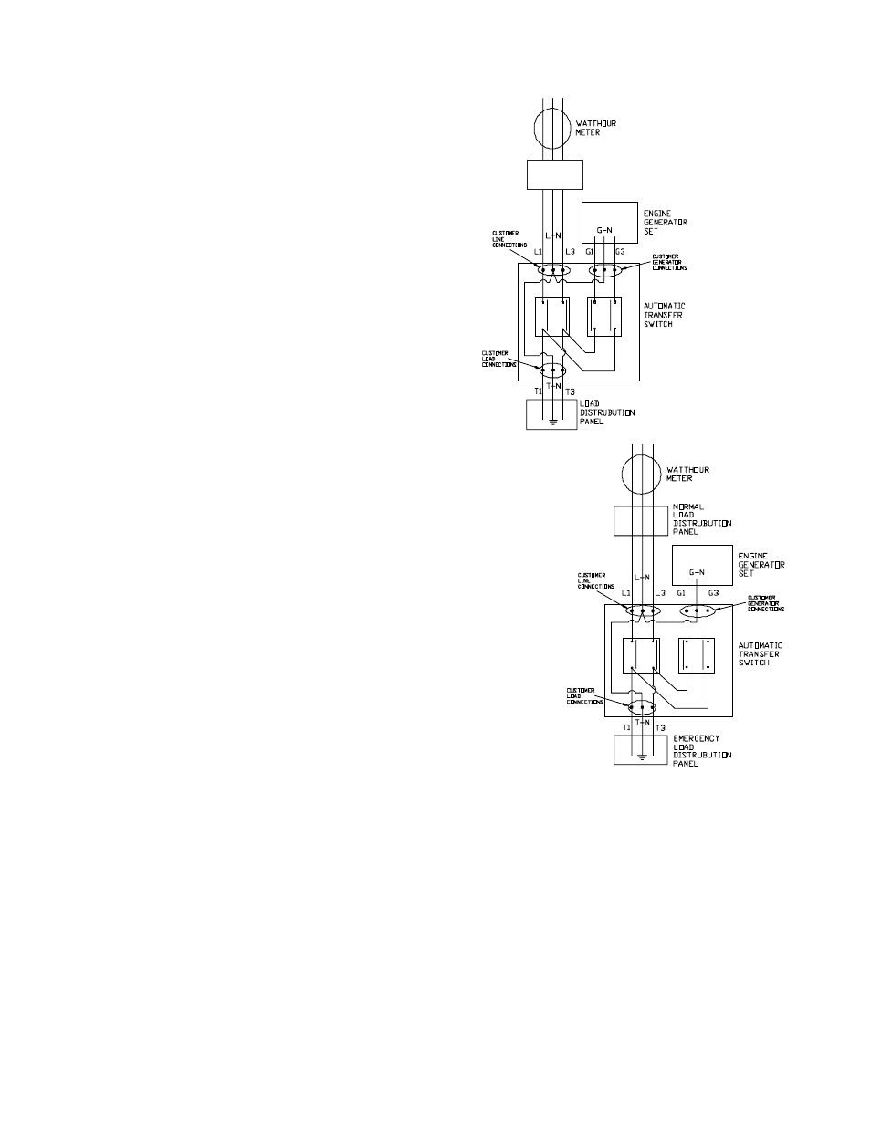
system, you will not be able to transfer the complete
electrical system. In this case it will be necessary to
install a secondary emergency distribution panel. See
Figure 4. NOTE: THE MAXIMUM OUTPUT OF THE
GENERATOR IS 40 AMPS AT 240 VOLTS. You must also
take this into consideration when deciding whether to
install an emergency distribution panel.
PSS12 - The Automatic Transfer Switch shipped with
the PSS12 system has a 110 Amp line side contactor
installed to handle your normal power needs and a 60
Amp generator side contactor to handle the emergency
generator output. Before installing the A.T.S. you must
first ensure that the 110 Amp line side contactor will be
sufficient to handle your complete service. See Figure 3.
(i.e. the main line breaker must not be larger than 110
Amps) If you have a 125, 150 , 200 Amp or larger
system, you will not be able to transfer the complete
electrical system. In this case it will be necessary to
install a secondary emergency distribution panel. See
Figure 4. NOTE: THE MAXIMUM OUTPUT OF THE
GENERATOR IS 50 AMPS AT 240 VOLTS. You must also
take this into consideration when deciding whether to
install an emergency distribution panel.
************
***** DANGER *****
*************
Be certain the operation selector switch on the front of the
A.T.S. Control is in the “stop” position and the main power
switch “off”. For your own protection, verify these impor-
tant safety precautions yourself with reliable instruments
before proceeding.
A.C. ELECTRICAL CONNECTIONS
*************
***** WARNING *****
*************
A FUSED DISCONNECT OR CIRCUIT BREAKER
MUST BE INSTALLED BETWEEN THE GENERATOR
AND THE A.T.S. PANEL TO PREVENT OVERLOADING
AND BURNING OUT THE GENERATOR. FAILURE TO
PROVIDE A FUSED DISCONNECT OR CIRCUIT
BREAKER, RATED AT GENERATOR RATING WILL VOID
YOUR WARRANTY IN CASE OF GENERATOR FAIL-
URE.
Generator Connections
To gain access to the customer connections first
remove the top cover and then remove the end panel
opposite the muffler. All connections including AC & DC
connections to the ATS, 120 Volt power connection for
battery charger, fuel line connection and battery installa-
tion are made behind this panel. After removing the end
panel you will need to remove the cover over the connec-
tion box in the upper right hand corner. Knockouts are
provided on the outside of the enclosure for your conve-
nience. Three AC power leads are required between the
generator and the A.T.S. a fourth lead will be required if
you are required by code to provide an isolated neutral.
The units are shipped with the neutral bonded to ground.
If you need to run an isolated neutral, you will need to
remove the generator neutral leads from the ground lug
mounting bolt where they are attached. You will then
need to run both a neutral and a ground lead in addition
to the two power leads all the way back to your distribu-
tion panel. The two power leads from the generator are
marked G1 and G3.
All power leads from the generator to the A.T.S. must
be sized to handle rated generator output amperage at a
minimum, the type of wire you use will determine the
gauge required. Consult your local wire supplier for
proper gauge and type for your area.
FIGURE 3
FIGURE 4
Service Entrance
Circuit Breaker