Mounting the automatic transfer switch (a.t.s.) – Winco PSS20000/C User Manual
Page 10
PAGE 8
attached to it, this is where you will connect your 120 volt
fused power feed. If you are installing the optional block
heater on the PSS8000, you should also connect the
power feed for the block heater here. The PSS20000 has
a duplex receptacle mounted on the rear engine support
bracket. The wires for this receptacle have been routed
up into the generator connection box for your conve-
nience. You will make your connection from your 120 volt
power feed in the connection box. The block heater can
then be plugged into the extra receptacle on the duplex.
** NOTICE **
The battery tender is not intended to recharge a battery
which has become completely discharged. It is de-
signed to produce enough current to recharge a slightly
low battery, maintaining it fully charged.
MOUNTING THE AUTOMATIC
TRANSFER SWITCH (A.T.S.)
*************
***** WARNING *****
*************
EQUIPMENT DAMAGE- Protect the switch from construc-
tion grit and metal chips to prevent a malfunction or
shortened life of the switch. Contactors returned for
warranty consideration wilth foreign material inside of
them will not be warranted.
The Automatic Transfer Switch connects the load
(lights, furnace, outlets, etc.) to the normal power line
during standby. When normal power fails, the A.T.S.
starts the engine generator set, disconnects the power
line and then connects the load to the standby generator
set. When normal power is restored, the automatic
switch retransfers the electrical load to the normal
service and stops the engine. The A.T.S. panel should
be mounted as close to the distribution panel as
possible.
*****NOTE*****
EQUIPMENT DAMAGE- The standard NON-UL Winco
ATS does not protect against undervoltage. If you are in
an area that is suspectibly to brown outs (low voltage)
you may want to consider adding an undervoltage sensor
to standard ATS panel.
*************
***** WARNING *****
*************
All wiring must be done by a licensed electrician, and
must conform to the national electrical code and comply
with all state and local codes and regulations. Check with
your electrical inspectors before proceeding!
PSS8000 - The Automatic Transfer Switch shipped with
the PSS8000 system has a 110 Amp line side contactor
installed to handle your normal power needs and a 60
Amp generator side contactor to handle the emergency
generator output. Before installing the A.T.S. you must
first ensure that the 110 Amp line side contactor will be
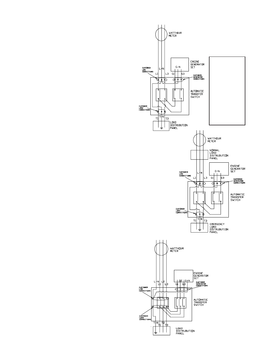
sufficient to handle your complete service. See Figure 3.
FIGURE 3
FIGURE 4
FIGURE 5
NOTE:
The PSS12000
generator
connections are
numbered
differently. Use
extreme caution
when connecting
generator to the
transfer switch.
See installation
paragraph for
proper wire
connections.