Winco HPS12000HE/F User Manual
Page 8
3240-10
8
60706-236
Natural Gas
2
3
4
UNIT OFF
LINE PSI 7-11 in
7-11 in
4-6 oz
4-6 oz
STARTING
LINE PSI 7-11 in
7-11 in
4-6 oz
4-6 oz
NO LOAD
LINE PSI 7-11 in
7-11 in
4-6 oz
4-6 oz
FULL LOAD
LINE PSI 7-11 in
7-11 in
4-6 oz
4-6 oz
Remember that whichever fuel delivery system or
type of vapor fuel used, the fuel pressure at the
demand regulator installed on the engine generator
must be between 4 and 6 oz. (7-11 inches of water
column). Any lower pressure and the unit will starve
for fuel under load. Any higher and the unit will ‘fl ood’
when attempting to start.
LP TANK SIZING
The tank sizes shown below are the smallest recom-
mended tank sizes based on the outside temperature.
Once above this minimum acceptable size, the size of
L.P. tank used will generally depend on how long you
want the unit to run without refi lling. Keep in mind
the colder it gets the slower L.P. will vaporize. This
is the reason for the larger tanks at low temperature.
Minimum sizing is not based on running time.
Temp f.
60 deg
30 deg
0 deg
-20 deg
150 gal
250 gal
500 gal
1000 gal
CHANGING FUEL TYPES
These engine generator sets are designed to run
on three different fuels; gasoline, natural gas or LP
vapor. They may be easily changed from one fuel to
another.
FROM GASOLINE TO LP/NG
1. With the engine running turn off the gasoline
fuel valve.
2. Run the engine until it runs out of fuel.
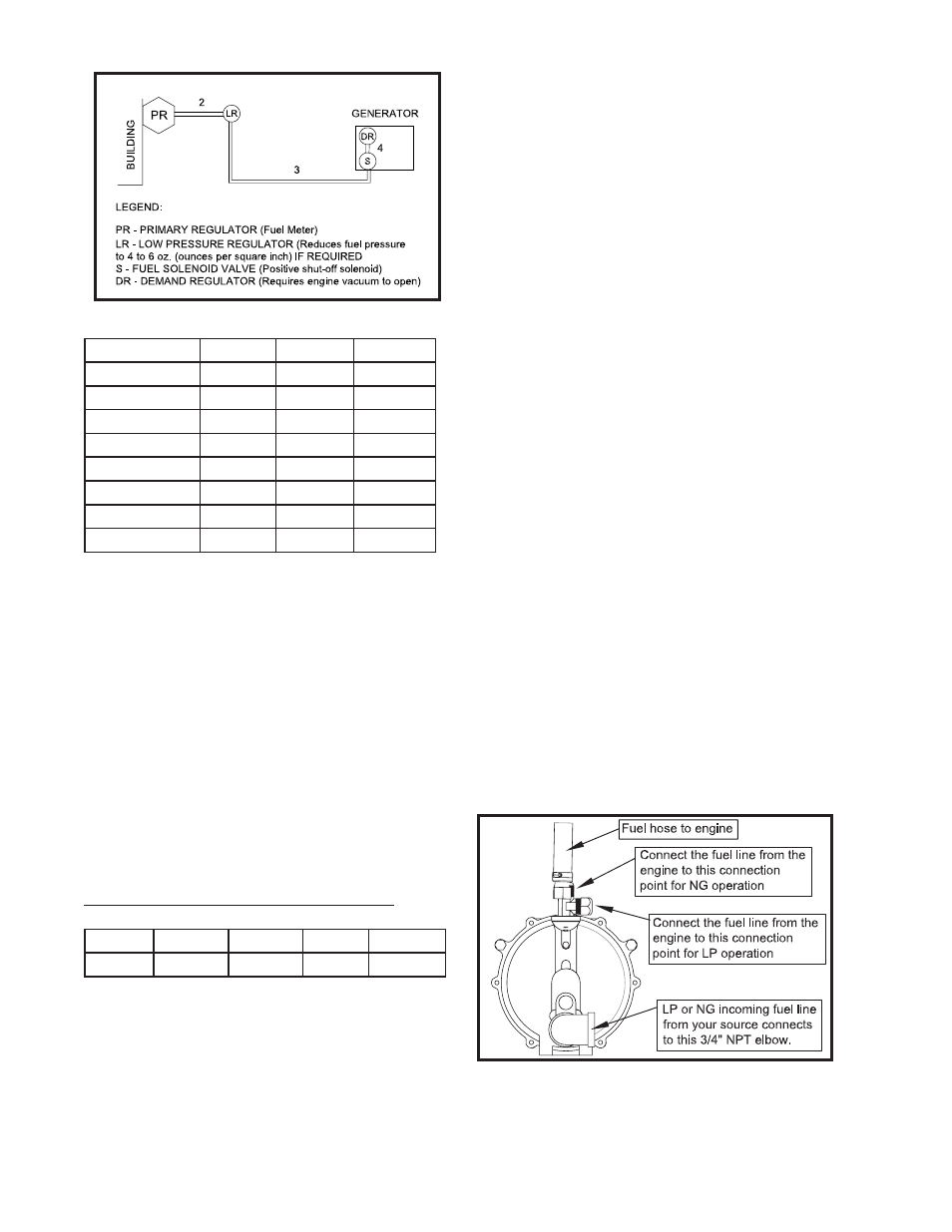
3. Remove the plastic insert from the demand
regulator.
4. Install a locally approved fl exible fuel line.
5. Connect the LP/NG vapor fuel line to the fl ex-
ible fuel line. You can’t connect the black iron
pipe dir
6. All three units have two different hose fi ttings
on the top of the demand regulator. One is for
LP and one is for Natural Gas. Make sure the
hose is attached to the proper fi tting. See the
picture below.
7. Turn on the vapor fuel.
8. Start the engine.
9 . Apply the load to the generator.
FROM LP/NG TO GASOLINE
1. With the engine running turn off the LP/NG
fuel supply.
2. Run the engine until it runs out of fuel.
3. Remove
the
fl exible fuel line from the demand
regulator.
4. Reinstall the plastic insert in the regulator.
5. Check to be sure the gasoline fuel valve is off.
6. Fill the gasoline fuel tank.
7. Turn on the gasoline fuel valve.
8. Start the engine.
If the optional FUEL SOLENOID kit has been in
stalled on the unit all vapor fuel connection will be
made at the 12 volt gas valve.