Testing rectifiers – Winco Rotating Field Design Troubleshooting Guide User Manual
Page 3
b.
The resistance values are shown in table #1.
c.
There should not be any reading to ground.
19.
Check Stator Output power leads for continuity, resistance and grounding.
a.
There should be continuity between leads.
b.
The resistance values are shown in table #1.
c.
There should not be any reading to ground.
20.
Check for continuity between the rectifier leads and power leads from the stator.
a.
There should not be continuity between these two sets of leads.
19.
Remove brush rack and check brushes for spring tension, binding, burning, and
a minimum of 3/8 in. length.
20.
Check rotor slip rings for wear and corrosion.
21.
Check rotor slip rings for continuity and grounding.
a.
There should be continuity between slip rings.
b.
The resistance values are shown in table #1.
c.
There should not be any reading to ground.
22.
Replace any defective parts and reassemble generator.
23.
Flash field according to diagram #1.
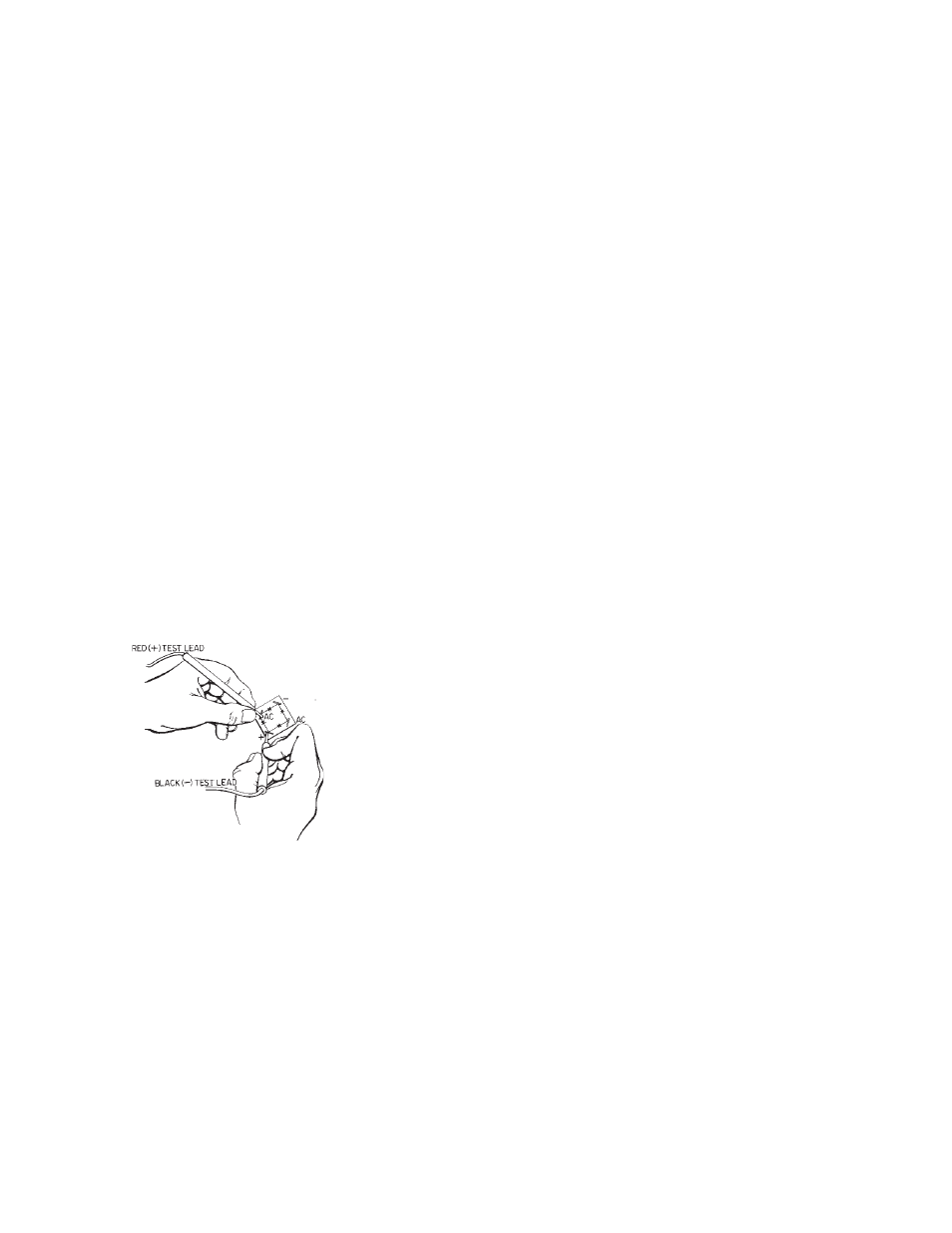
TESTING RECTIFIERS
The field excitation is supplied through a full wave bridge rectifier. This type of rectifier has four
terminals - two AC, one DC positive and one DC negative. There are 4 diodes within each
rectifier, one between each of the terminals as you go around the outside of the rectifier.
The rectifier is tested in the following manner:
1.
Disconnect all leads from rectifier.
2.
Connect the red ohmmeter lead to the positive DC (+)
terminal.
3.
Connect the black lead to each of the AC terminals in turn.
Either a high or low resistance reading will be obtained.
4.
Reverse the meter leads, black lead to the DC POS (+)
and red lead to the AC terminals, each in turn. An opposite
reading should be observed.
5.
Connect the red ohmmeter lead to the negative DC (-)
terminal.
6.
Connect the black lead to each of the AC terminals in turn. Either a high or low
resistance reading will be obtained.
7.
Reverse the meter leads, black lead to the DC NEG (-) and red lead to the AC
terminals, each in turn. An opposite reading should be observed.
8.
Check each terminal to the case. An open circuit (very high resistance) reading
should be observed.
9.
If the rectifier fails any of the above tests, it should be considered defective and
replaced.
If a battery powered test light is used. Follow the same procedures described below. A good
diode element will allow current to pass to the light in the test lamp in only one direction.
Page 3