Locating stove, Page 6 – Vogelzang VG820E User Manual
Page 6
Page 6
/
VG820E HEARTWOOD™
VGZ-010 / 20120105.0
LOCATING STOVE
1. The stove must be placed on solid concrete, solid
masonry, or when installed on a combustible floor,
a solid-surface, non-combustible floor protec-
tion must be placed beneath the unit and extend
8˝/203mm beyond the sides, 16˝/406mm to back-
side, and 18˝/457mm beyond the front of the fueling
and ash removal doors. The floor area beneath
stove and extending 8˝/203mm beyond each side
of the flue elbow and chimney connector
must
be covered with a solid-surface non-combustible
insulated floor protector. All manufactured floor pro-
tection must be listed to UL 1618 Type 2 and have
an
R-value of 2.7 or equivalent. Floor protection
must have a
minimum thickness of 1˝/254mm.
Minumum floor protector dimensions must be
43˝x 60˝/109.2cm x 152.4cm. (NOTE: To calculate
R-values of equivalent alternative materials, see
page 19). Please reference figures 3–5 and consult
and follow local building codes and fire protection
ordinances.
2. The stove must have its own flue.
DO NOT CON-
NECT THIS UNIT TO A CHIMNEY FLUE SERVING
OTHER APPLIANCES.
3. After observing the clearances to combus-
tible materials (figures 3–5), locate your floor
protector accordingly (figure 3) and careful-
ly place the stove in your selected location.
Install stove pipe, elbows, and thimble as
required, utilizing either a recently cleaned and
inspected 6˝/152mm masonry chimney or a
6˝/152mm i.d. listed chimney.
4. Use 6˝/152mm diameter minimum 24 MSG Black
or 26 MSG Blue round stove pipe. DO NOT USE
GALVANIZED stove pipe. Secure pipe sections with
three (3) sheet metal screws in each stove pipe
and/or elbow joint to firmly hold the pipe sections
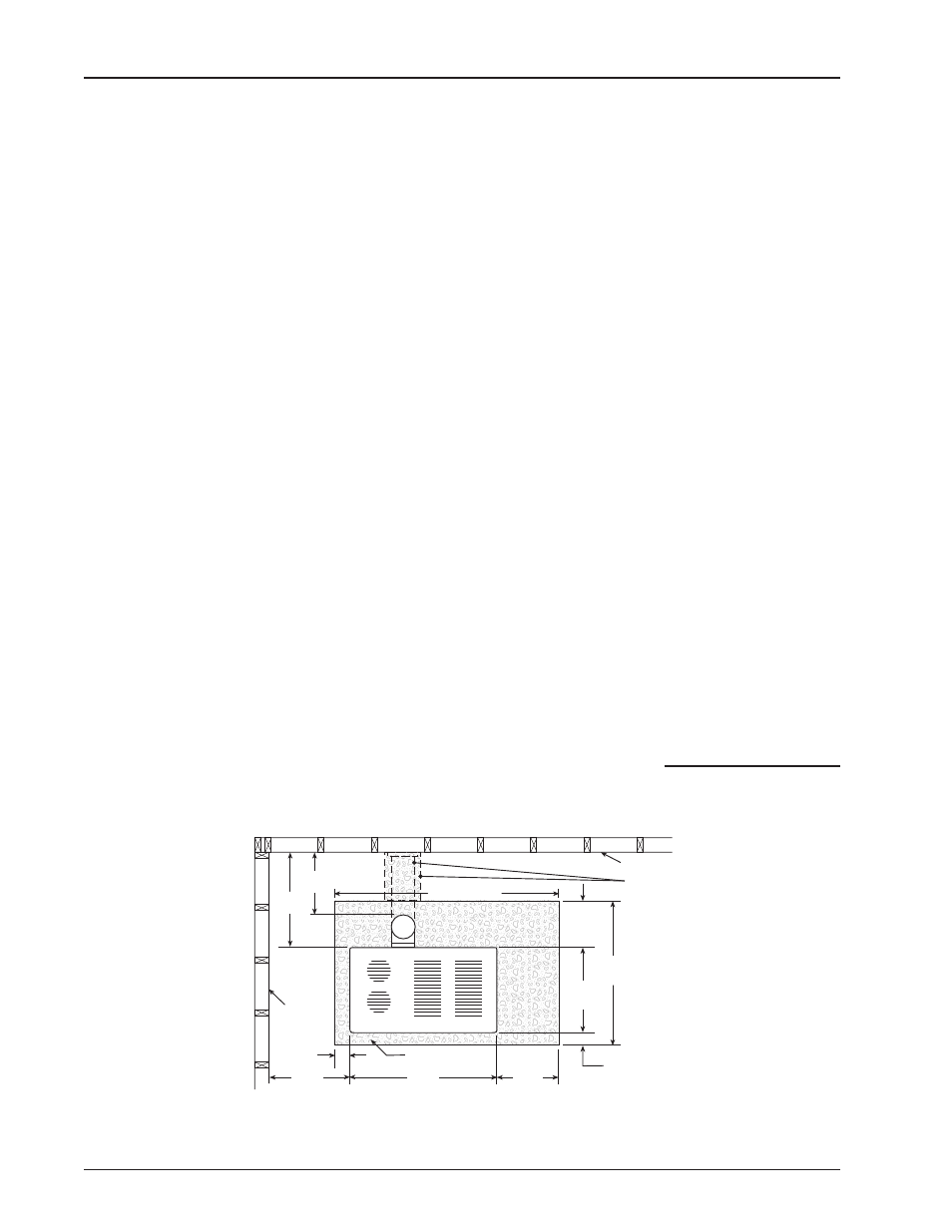
Fig. 3 – Minimum Clearance Dimensions from Combustible Surfaces for USA & CANADA
FLOOR PROTECTOR
COMBUSTIBLE CONSTRUCTION IN ACCORDANCE WITH NFPA 211
BACKWALL
SIDEWALL
16"/
40.6cm
19"/
48.3cm
43"/
109.2cm
8"/20.3cm
8"/
20.3cm
18"/
45.7cm
32"/
81.3cm
20"/
50.8cm
60"/152.4cm
18"/
45.7cm
34"/
86.4cm
TOP VIEW
NOTE: DASHED LINES SHOW
STRAIGHT OUT CHIMNEY CONNECTOR
AND ADDITIONAL FLOOR PROTECTOR
REQUIRED BENEATH AND EXTENDING
8˝/203MM ON EITHER SIDE OF
CONNECTOR PIPE
together.
DO NOT CONNECT THIS STOVE TO
ANY AIR DISTRIBUTION OR DUCT SYSTEM.
5. R e c h e c k c l e a r a n c e s f r o m t h e s t o v e ,
connector stove pipe, and corner clearanc-
es using the illustrations in figures 3–5 and
your local building codes or fire protection
ordinances.
NOTE: ANY WALL CONTAINING COMBUSTIBLE
MATERIALS SUCH AS WOODEN STUDS OR
DRYWALL FACED WITH BRICK OR STONE
MUST BE CONSIDERED A COMBUSTIBLE
SURFACE.
6.
DO NOT INSTALL THIS STOVE IN A MO-
BILE HOME, TENT OR TRAILER. (NO
EXCEPTIONS)
7. The clearances provided are minimum di-
mensions set by UL standard 1482-2011 &
ULC-S627-00, tested and applied by Warnock-
Hersey Test Laboratories, Inc. the manufacturer’s
testing agency. Installation of this stove must
comply with the latest edition of NFPA 211 (USA)/
CAN/CSA-B365 and/or your local building code
rulings. Use whichever minimum dimensions are
LARGEST.
Clearances listed and shown MUST be adhered to
for safe operation of this appliance.
CLEARANCES
MAY NOT BE REDUCED BY ANY MEANS IN USA
OR CANADA.
8. This stove meets Test Standards: UL 1482-2011 &
Canadian Standard: ULC-S627-00.
Failure to follow these minimum clear-
ance requirements may result in an unsafe
installation and could cause a fire.
Continued on next page