Locating stove . . . continued – Vogelzang TR007 User Manual
Page 7
VGZ-031 / 20120619.1
www.vogelzang.com
TR007
PONDEROSA™ /
Page 7
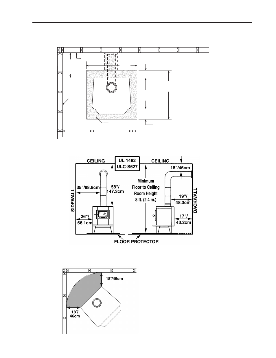
LOCATING STOVE . . . continued
Figure. 4 – TOP VIEW Minimum Clearance Dimensions from Combustible Surfaces
continued on next page
FLOOR
PROTECTOR
DASHED LINES SHOW HORIZONTAL CHIMNEY CONNECTOR
AND ADDITIONAL FLOOR PROTECTOR REQUIRED BENEATH
AND EXTENDING 2"/50.8mm BEYOND
EACH SIDE OF CONNECTOR PIPE
COMBUSTIBLE CONSTRUCTION IN ACCORDANCE WITH US NFPA 211
BACKWALL
SIDEWALL
30"/76.2cm
56"/142.3cm
18"/46cm min.
8"/21cm min.
8"/21cm min.
24"/61cm
26"/66.1cm
min.
17"/
43.2cm
min
CLEARANCES | TOP VIEW
40"/
102cm
Minimum
Clearances
for installation
according to
UL 1482 (US) &
ULC-S627 (CDN)
Figure 5a – Front View
Figure 5b – Side View
Minimum Clearance Dimensions
from Combustible Surfaces
Figure 6 – Top View
Minimum Corner Clearances
from Combustible Surfaces
18˝/46cm (US & CDN)