Assembly instructions – Vogelzang SR57E User Manual
Page 4
Page 4
/ SR57E
Vogelzang International Corp.
VGZ-004 / 20120328.0
tools
required
CAUTION: STOVE IS HEAVY. MAKE SURE YOU
HAVE ADEQUATE HELP AND USE PROPER
LIFTING TECHNIQUES WHENEVER MOVING
STOVE.
Refer to diagram and parts lists at back of this manual.
Refer to diagram and parts lists at back of this manual.
1. Uncrate the stove and remove cardboard packing
and protective poly bag. (Save cardboard for further
assembly.)
2. Remove par ts from inside of stove. Par ts
include: four lids (#1), three lid supports (#4 & #5),
one ash door (#14), one lid lifter (#16), four legs
(#15), hardware pack (#17), and Spring Handle
(#12) and draft damper (#18).
3. Place flattened carton on floor and carefully turn
stove over onto carton.
4. Attach the legs to base of stove with stove bolts.
5. Carefully lift stove upright and place in de-
sired location (see following instructions for
properly locating stove).
6. Place lid supports and four lids in position on stove
top.
7. Lower ash door into position.
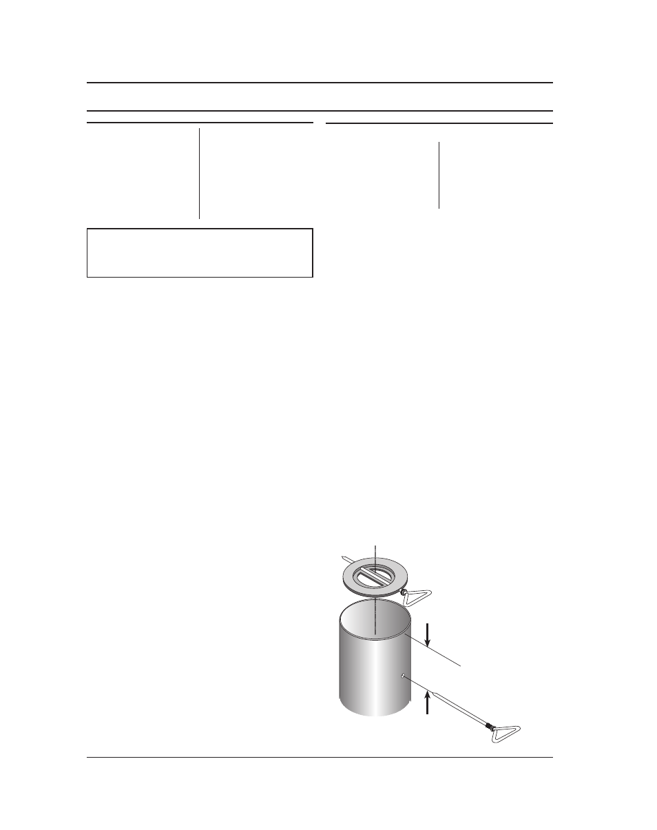
8. The flue pipe
draft damper (#18) must be installed
into the top end of the first straight section of stove
pipe (fig.1) exiting the stove
before the stove is
used.
ASSEMBLY INSTRUCTIONS
materials
required
(NOTE: The following items are NOT included with your stove)
a. Drill two 1/4” holes centered on either side of the
pipe section 6” from the top end of the pipe (figure
1).
b. Remove the handle from the damper then slide the
damper into the pipe.
c. Align the damper with the holes drilled in step 8a
and insert the handle through the holes and the
damper.
NOTE: THIS DAMPER IS NECESSARY FOR THE
PROPER OPERATION OF THE STOVE AND
TO MEET EPA EMISSIONS REQUIREMENTS
FOR HEATING APPLIANCES. IT MUST BE IN-
STALLED BEFORE USE. (NO EXCEPTIONS)
9. Attach stove piping — see instructions on page 5.
Screwdrivers
(blade and phillips types)
13mm Nut Driver or Ratchet
with 13mm Socket (for 13mm
Hex Nuts)
13mm Nut Driver or
Ratchet with 13mm Socket
(for Stove Bolts)
Safety Glasses
Hearth Gloves
Pencil
6 foot Folding Rule or
Tape Measure
Tin Snips
Drill: Hand or Electric
1/8” dia. Drill Bit
(sheet metal screws)
Flooring Protection: 56” x 59”
as specified (see page 4)
Chimney Connection: 6” black
steel (24 ga. min.) straight or
elbow (as required)
1/2” Sheet Metal Screws
Chimney: Existing 6” Lined Ma-
sonry Chimney or 6” Inside Dia.
manufactured chimney system
listed to UL 103 HT.
Furnace Cement (manufacturer
recommends Rutland Code 78
or equivalent)
6"/15.25 cm
DRAFT DAMPER
(must be installed
before use — NO
EXCEPTIONS!)
NOTICE: Vogelzang International Corp. grants no warranty, stated or implied, for the installation or maintenance of
your wood stove and assumes no responsibility of any incidental or consequential damages.
Fig. 1 – Draft
Damper Installation