Anatomy of the ec-3500 – CatEye EC-35OO User Manual
Page 2
LOADING
LEVEL
MODE
PULSE
CADENCE
TIME
WORK RATE
SPEED
CALORIE
PULSE
DISTANCE
ADVANCE
MODE
SET
TARGET
PULSE
ON/OFF
EC-35OO
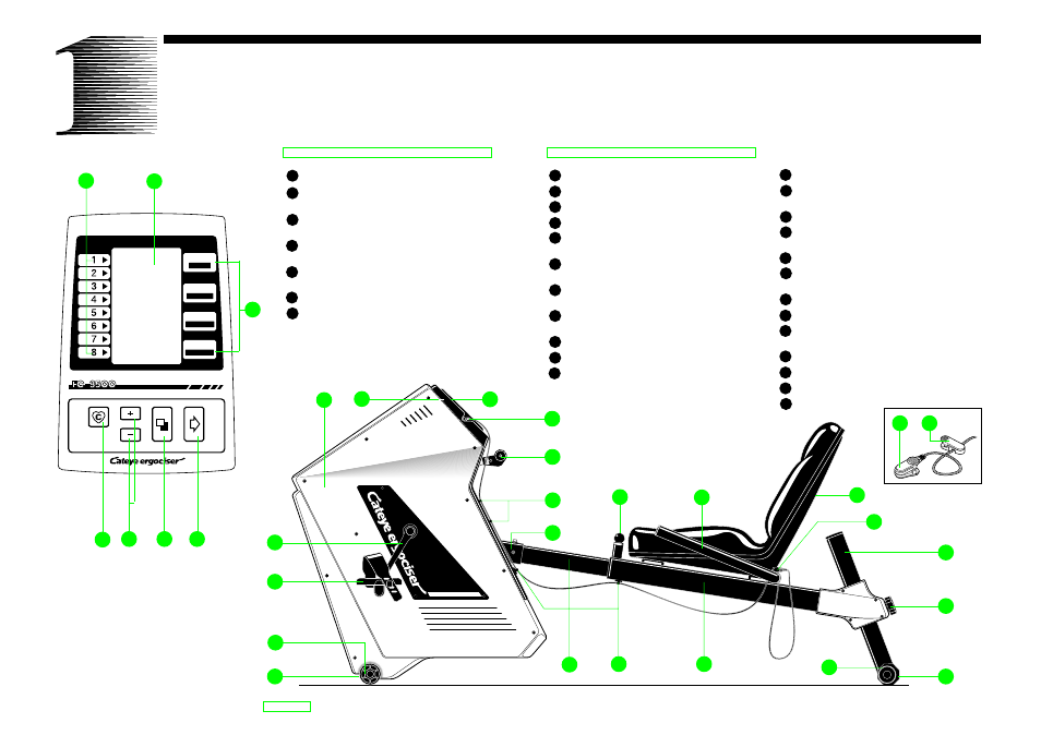
Control Panel
A
Display screen
B
Mode
(Indicates what each figure stands for.)
C
Advance Button
(Makes the program proceed to the subsequent stage.)
D
Mode Button
(Selects data to input or display.)
E
Set Button
(Modifies figures to input.)
F
Target Pulse On/Off Button
G
Loading Level
(Indicates grade of work load.)
ANATOMY OF THE EC-3500
2
1
2
22
21
20
19
3
F
D
C
E
G
A
B
Main Body
1
Main Unit
2
Control Panel Cover
3
Control Panel
4
Pulse Sensor Jack
5
Workload Shift Lever
(Changes workload level.)
6
Cable Hooks
(Holds pulse sensor cable.)
7
Joint
(Connects main body with rear frame.)
8
Seat Lock Pin
(Pull when adjusting seat position.)
9
Handlebar
10
Seat
11
Sensor Clip
(Holds sensor when not in use.)
12
Rear Support Pipe
13
Seat Height Lock Knob
(Loosen when adjusting seat height.)
14
Rear Leg
15
Level Adjuster
(For better stability of the unit.)
16
Seat Pipe
17
Cable Holder
(Holds pulse sensor cable.)
18
Inner Pipe
19
Front Leg
20
Caster
(For easy transportation of the unit.)
21
Pedal
22
Crank
23
Pulse Sensor
24
Cable Clip
18
17
16
15
14
13
12
10
11
23
24
9
8
4
5
6
7