USL IRC-21 User Manual
Page 6
- 5 -
- 6 -
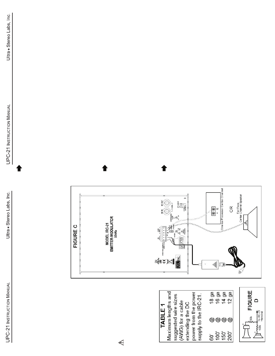
Connect the center channel speaker terminals to the + and - (ground) audio input terminals on the IRC-21 as in Fig C. If the center channel is bi-amped, you must construct a resistor network, as in Fig. D, that sums the high and low frequency signals, then feed the output of the network to the IRC-21 audio input.
Y
ou also may connect the IRC-21 input to the output of a monitor or a
processor
.
CONNECT THE
AUDIO INPUT LINE
CONNECT THE IRP-20 DC POWER P
ACK
Connect the provided IRP-20 DC power supply to the IRC- 21 power input terminals (1 and 2). If the DC supply cable needs to be extended, refer to table 1 for suggested wire sizes. Make sure there are no loose wire strands at the terminals to avoid potential short circuits.
DO NOT SHOR
T THE
POWER SUPPL
Y!
Connect the power supply to an
AC outlet (100 - 240V
AC,
50/60Hz) using the supplied or a standard IEC power cord.
PRELIMINAR
Y
LEVEL
SETTING
Run program material with HI audio. Set the compression slope to 2:1.
Adjust the appropriate DIP
switches and input level controls to cause the audio
level LEDs to flash druing normal programming, but not to stay lit continuously
.
T
ry listening on IR headphones. If necessary
, adjust compression to bring up
low levels or reduce noise.
Note: The IRC-20 has an automatic shutof
f circuit. The unit will
shut itself of
f after a thirty-minute absence of audio input.
When the audio resumes, the panel will switch on immediately
.
Mounting the Emitter/Modulator at the front of the auditorium
(See Figures F and G)
Attach the supplied mounting bracket to the wall surface
and use the supplied screws to attach the bracket to the emitter
. Allow free airflow
around the emitter and be sure to have at least eight inches clearance from all
surfaces, preferably more if at all possible.
The rear panel is used as a heat sink
and the heat must be allowed to dissipate.
The unit should be mounted to the side
of the screen/stage area, 12 to 15 feet above the audience’
s heads and pointed
downward and into the seating area.
Mounting the Emitter/Modulator at the rear of the auditorium
Attach the supplied mounting bracket to the wall surface and use the supplied
screws to attach the bracket to the emitter
. Allow free airflow around the emitter
and be sure to have at least four inches clearance from all surfaces, preferrably
more.
The rear panel is used as a heat sink and must be allowed to dissipate heat.
The emitter will cover up to 5,500 square feet (60 x 84 feet).
The emitter is typi-
cally mounted near the projector window
. The panel should be “aimed” towards the
screen.
This typically results in the panel being vertical and parallel to the rear wall
of the auditorium.
Aiming the panel towards the screen provides additional audito-
rium coverage from screen reflection.
CAUTION: The rear panel may get quite warm to the touch. This is normal.