USL UPC-21 User Manual
Page 4
- 3 -
1. Main Connector; consisting of the following:
a. Pins 1 & 2: DC Power Input Terminals.
Connect the output leads of the USL supplied 32VDC power
supply to pins 1 and 2. Connect the red wire to pin 1.
b. Pin 3: AC Ground Terminal.
This terminal may be connect to an earth ground connection
if required by local building codes.
c. Pin 4: Audio System Ground.
Connect to the shield of shielded-pair input cable.
d. Pin 5 & 6: Audio Input Terminals.
Balanced, differential input. Connect the two wires of a shielded
pair input cable to these terminals. If the source is unbalanced,
connect one of the wires to the shield at the source end of
the cable to minimize ground loop noise.
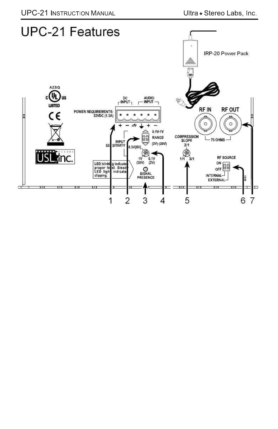
2. Input Range Selector.
With both switches in the upper position, the audio channel input level
range is 0.1 to 1.0 Vrms. With both switches in the lower position, the
input range is from 2 to 20 Vrms (suitable for speaker amplifier output
levels).
3. Signal Presence Indicator.
Indicates proper audio level when light blinks at the peaks of the sound.