6 antenna – TruTrak KRT2 Comm Radio IR User Manual
Page 30
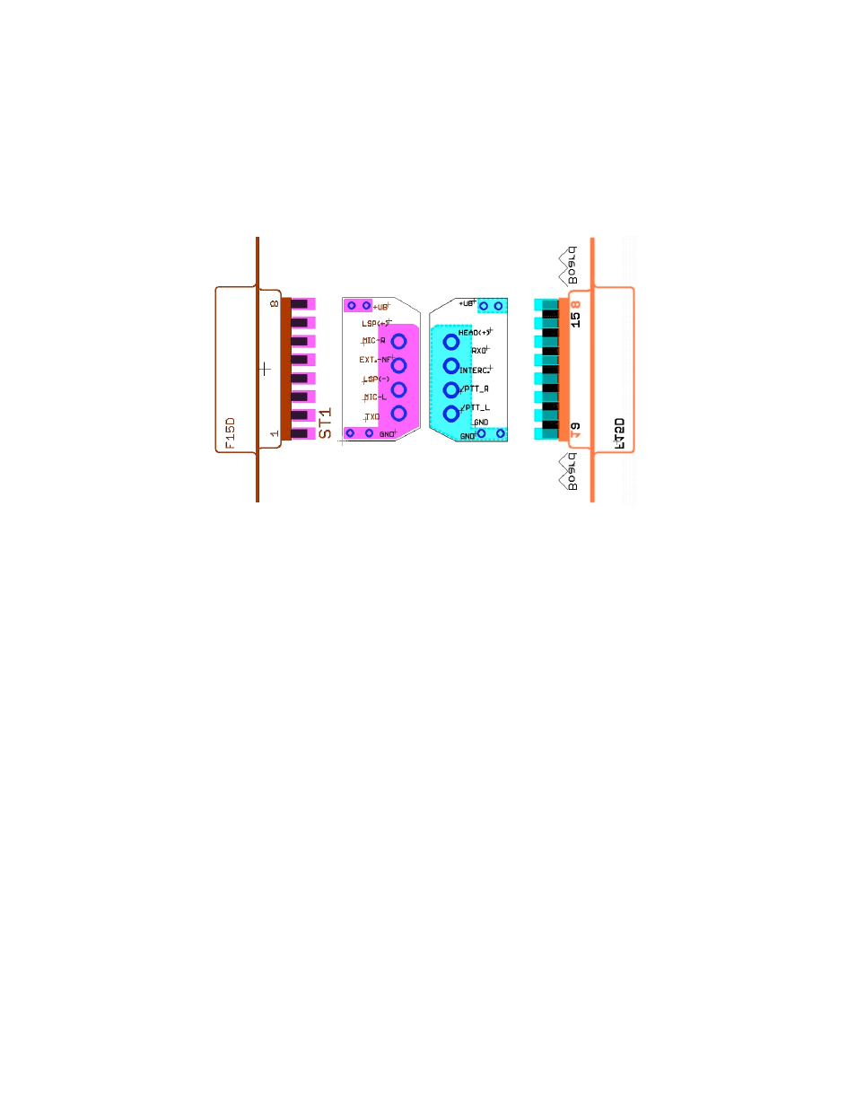
4.5.4
Connection
Support
In
order
to
connect
shields
of
all
cables
at
a
single
point
and
to
avoid
ground
loops
an
adapter
board
as
shown
is
recommended.
The
adaptor
board
and
connectors
have
been
provided
with
the
KRT2
The
adapter
board
is
placed
between
the
connector
pin
rows
and
soldered
to
the
BAT
plus
pins
8,
15
and
GND
pins
1,
9.
Further
information
printed
on
the
board
serves
to
connect
all
cables
to
its
corresponding
pins.
4.6 Antenna
4.6.1 Antenna Selection
•
A
50
Ohms
impedance
VHF-‐COM-‐antenna
is
required.
•
The
antenna
must
be
approved
in
respect
to
aircraft
type
and
installation
location.
•
The
antenna
specifications
can
only
be
fulfilled
when
properly
installed.
4.6.2 Installation Recommendation
•
The
manufactures
instructions
have
to
be
observed.
•
The
metallic
contact
between
airplane
surface
and
antenna
ground
must
be
very
good.
Non-‐metallic
airplanes
must
have
installed
a
metal
sheet,
foil
or
mesh
of
at
least
80×80
cm
inside
the
fuselage
as
electric
counterweight..