Electrical pin-out – TruTrak ADI Pilot II User Manual
Page 13
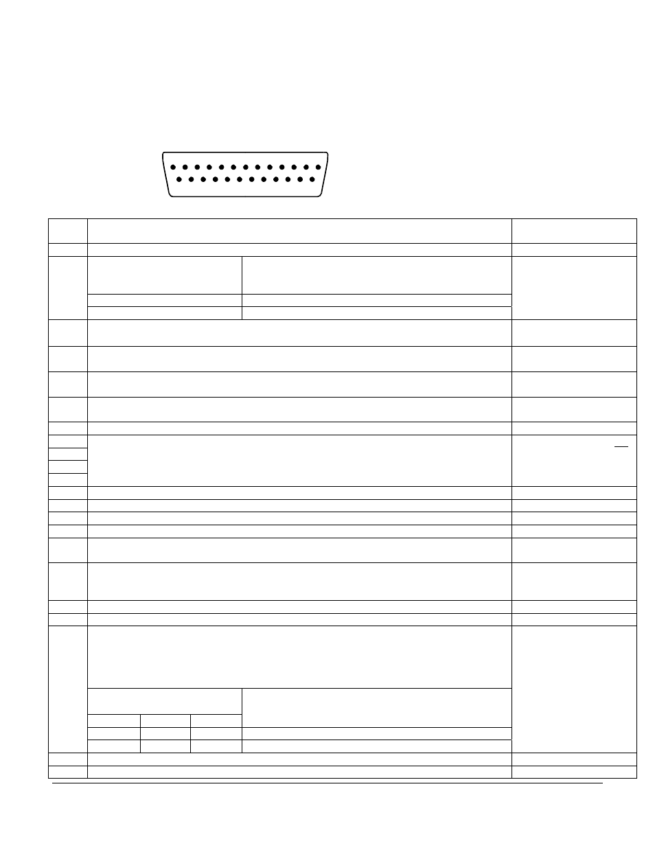
Electrical Pin-Out
ADI Pilot I and ADI Pilot II autopilots have similar wiring requirements. Therefore, this manual covers all such units, with
special notations covering any differences between the units. The table below provides a brief explanation of each pin function
on the main 25-pin connector P101. Note that the ADI Pilot I does not use pins 1,2,4,5,8,9,10,11, as it does not have a pitch
servo.
P101
Pin
Function Notes
1 Dedicated ground connection for Pitch Reverse Jumper.
Pitch Reverse Jumper,
present or absent, as follows:
Direction of servo arm / capstan rotation
(as viewed from face of the servo body)
for UP elevator
Pin 2 open (no connect):
Servo CCW (counter-clockwise) Î UP
2
Pin 2 Jumpered to pin 1:
Servo CW (clockwise) Î UP
See note 3 on wiring
diagram
Pins 1,2,4,5,8,9,10,11 are
for ADI Pilot II only
Control Wheel Switch. Connect as shown in wiring diagram to a SPST momentary switch
located remotely to the autopilot for convenient engage/disengage function.
3
Pitch Servo Torque Control. A signal from the autopilot to the pitch servo which sets the
amount of torque to be delivered by the servo.
Pins 1,2,4,5,8,9,10,11 are
for ADI Pilot II only
4
Pitch Servo Trim Sensor. A signal from the pitch servo to the autopilot which indicates an
out-of-trim condition and its direction.
Pins 1,2,4,5,8,9,10,11 are
for ADI Pilot II only
5
6 Autopilot Master (+12 to +28 V DC). The autopilot itself draws less than 0.5 ampere. Most of
the current required by the autopilot system is used by the servos (up to 1A per servo).
Use 5 Amp CB for ADI
Pilot system.
7 Auxiliary RS-232 Output. Presently unused, intended for future expansion.
8
9
10
11
Pitch Servo control lines. These lines cause the stepping motor in the pitch servo to run in the
appropriate direction at the desired velocity. They are small-signal lines and do not have any
substantial current-carrying capability or require any special shielding. Connect to pitch servo
as shown on wiring diagram.
ADI Pilot II only. Do not
attempt to reverse servo
direction by swapping
wires.
12 Reserved. Do not connect to this pin.
13 Ground Connection. Provide #20 AWG to common grounding point.
14 Reserved. Do not connect to this pin.
15 Reserved. Do not connect to this pin.
16 Roll Servo Torque Control. A signal from the autopilot to the roll (aileron) servo which sets
the amount of torque to be delivered by the servo.
17 Primary Serial Input. Baud rate selectable 4800 or 9600 baud. Automatically decodes
NMEA-0183, Garmin Aviation Format, or Apollo/UPSAT Moving-Map or GPSS format.
Provides directional reference to the autopilot.
18 AOA input, Future option
19 Autopilot Master (+12 to +28 V DC). Internally connected to pin 6
20
21
22
23
Roll (aileron) Servo control lines. These lines cause the stepping motor in the roll servo to run
in the appropriate direction at the desired velocity. They are small-signal lines and do not have
any substantial current-carrying capability or require any special shielding. Connect to roll
servo as shown on wiring diagram.
Reverse servo direction if
necessary by swapping
wires on pins 20 and 21.
See note 2 on wiring
diagram.
Wiring to roll servo J201
J101 Pin 20
Pin 21
Direction of servo arm / capstan rotation
(as viewed from face of the servo body)
for RIGHT aileron
Standard J201-4 J201-5 Servo
CCW
(counter-clockwise)
Î RIGHT
Reversed J201-5
J201-4
Servo CW (clockwise) Î RIGHT
24 24 Volt Dimmer Input Dimming for display and internal backlighting.
Must be dimming control
25 12 Volt Dimmer Input Dimming for display and internal backlighting.
system, not
Potentiometer.
1
20 21 22 23 24 25
2
3
4
5
6
7
8
9
10 11 12 13
14 15 16 17 18 19
Rear 25-Pin Connector P101
viewed from rear of unit or
wire side of connector
TruTrak Flight Systems
ADI Pilot I & II Autopilot Installation Manual
December 2009
11
8300-012 Rev B