6 wiring diagram, 7 j1 connector pin mapping chart – Trio Avionics EZ Pilot - v 1.9 User Manual
Page 39
35
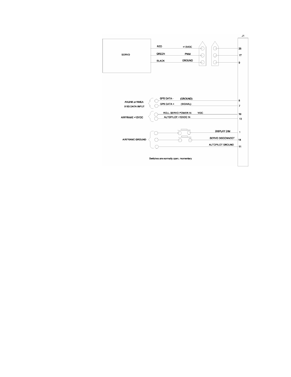
8.6 Wiring Diagram
8.7 J1 Connector Pin Mapping Chart
Pin
Function
Min Wire Size
Signal Type
Function
1
Remote Dim / Mode
26
data
momentary ground
2
Reserved
data
DO
NOT
USE
3
Reserved
data
DO
NOT
USE
4
reserved
data
DO
NOT
USE
5
reserved
data
DO
NOT
USE
6
reserved
data
DO
NOT
USE
7
GPS NMEA 0183 data in
26
data
gps RS232 serial data input
8
GPS Data return
26
data
signal ground
9
airframe ground
24
power
ground
2
10
GPS Data return (reserved)
26
power
signal ground
11
roll servo / airframe ground
24
power
ground
2
12
reserved
24
power
DO
NOT
USE
13
airframe +12VDC power
24
power
main power input
3
14 autopilot
disconnect
26 data
momentary
ground
15 airframe
ground
24 power
ground
2
16
spare
26
data
17
roll servo PWM out
26
data
shielded wire required
1
18
reserved
19
roll servo power input
24
power
power to roll servo
3
20
reserved
21
reserved
22
reserved
23
reserved
24
reserved
25
roll servo power output
24
power
switched power to roll servo
Notes:
1
These signals should be run in a shielded cable along with the appropriate ground signal. Ground the cable
shield at the EZ Pilot end and to a servo mounting screw at the servo end of the shield.
2.
Power ground wiring should originate at the airframe ground point.
3.
The circuit breaker used to provide power for these inputs should be sized according to the size of the wire
. being used to provide power to the circuit. For 24 gauge wire, a 3 amp circuit breaker/fuse is appropriate.