Toa WT-3810 User Manual
Page 3
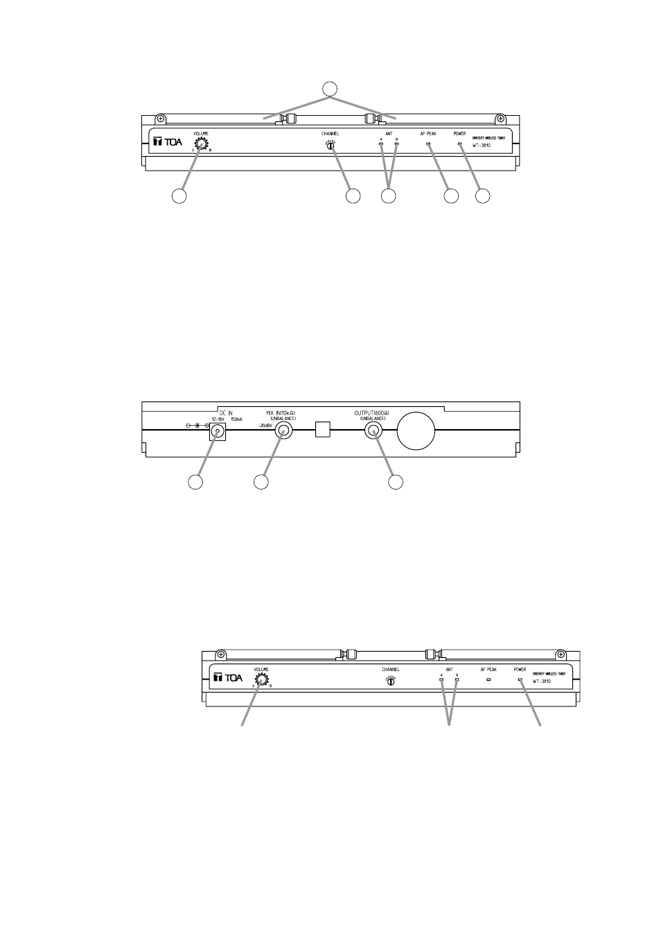
5. NOMENCLATURE AND FUNCTIONS
[Front]
[Rear]
1
2
3
4
5
6
7
8
9
1. Antenna
Raise the two antennas at a 45° angle outwards
from a vertical line. Do not raise the antennas
when carrying the tuner.
2. Volume control
Controls the output level.
3. Channel select switch
Used to select the frequency. (The tuner
frequency must be identical to that of the
microphone.)
4. Reception lamps
Either lamp, A or B, lights yellow when the tuner
receives a radio signal.
5. AF peak lamp
Lights red when the tuner output level reaches the
point about 3 dB below the clipping level.
6. Power lamp
Lights green when the DC power is supplied from
the DC power supply unit to the tuner.
7. AF output
Unbalanced phone jack
–20 dB/600
Ω. (0 dB = 1 V)
8. AF mixing input (unbalanced)
Connects to other unit's AF output.
Input level: –20 dB, 10 k
Ω (0 dB = 1 V)
9. DC input jack
Connects to the DC power supply unit. Because
the tuner is equipped with no power switch, it
automatically turns on when the DC power supply
is connected to this jack and wall AC outlet.
Disconnect the DC power supply unit from the AC
outlet when the tuner is not in use.
6. OPERATION
Step 1. Connect the DC power supply unit to the unit's DC input jack and wall AC outlet.
The power is turned on and the power lamp lights.
Step 2. Set the wireless microphone switch to the ON position.
The reception lamp lights when the tuner receives the same frequency signal.
Step 3. Adjust the volume control.
The output level increases as the volume is turned clockwise, and decreases as turned
counterclockwise.
2
3
1