Toa N-8640SB User Manual
Page 3
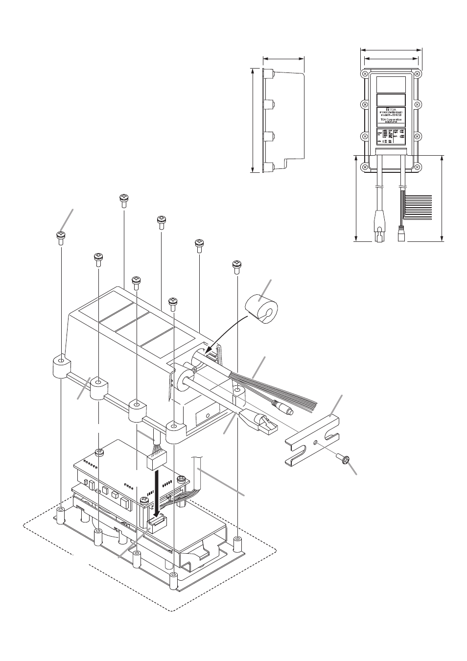
Step 5. Run the connection cables through the case’s cable
entry holes, then make cable connections.
5-1.
Run the LAN connection cable through the case’s
cable entry hole on your left, then connect it to the LAN
connector on the Main PC board.
5-2.
Run the power supply and external input/output
connection cable connected to the Sub PC board in step
3 through the other cable entry hole from the inside of
the case, then pull it out.
Step 6. Screw the case to the sleeves fixed to the operation
panel.
Step 7. Secure the cables to the case.
7-1.
Install the cord bush to each cable.
7-2.
Screw the cord bush fixing bracket to the case while
pressing both cord bushes with it.
[Dimensional diagram for the completed assembly]
Unit: mm
Note
A slit is provided on each cord bush.
Install the cord bush with its slit
facing inward.
7
-1
7
-2
5
-2
6
5
-1
Cord bush
Machine screw (with plain
and spring washers)
M3 x 8
LAN connector
LAN connection
cable
Cord bush fixing bracket
Tapping screw 3 x 8
Power supply and external
input/output connection cable
Power supply and external
input/output connection cable
Case
LAN connection cable
53
79
69
134
(135)
(130)
Note
Numerical values in parentheses
are for reference only.