Assembling – Toa N-8640SB User Manual
Page 2
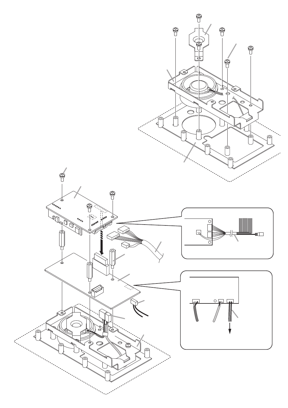
4. ASSEMBLING
Step 1. Place the Case gasket onto the operation panel, then
screw the chassis and speaker bracket to the operation
panel.
Step 2. Connect the connection cables and harness to the
Main PC board, then secure the Main PC board to the
chassis.
2-1.
Connect the speaker and microphone connection
cables (fitted with a connector) from the chassis to the
Main PC board. Connect between the Call switch on
the operation panel and Main PC board using the Call
switch connection harness.
Note
If no Call switch is installed on the operation panel,
connect the external control input cables to the external
switch. (See Example 3 on p. 4, “Connections.”)
2-2.
Secure the Main PC board to the chassis using the
sleeves.
Step 3. Connect the power supply and external input/output
connection cable to the Sub PC board.
Step 4. Join the connector on the Sub PC board and that on the
Main PC board together, then screw the Sub PC board
onto the sleeves.
Chassis gasket
Chassis
Speaker bracket
Machine screw (with plain
and spring washers) M3 x 8
1
Viewed from the component side
Viewed from the rear side
Power supply and
external input/output
connection cable
Power supply and
external input/output
connection cable
2
-1
2
-2
4
4
3
Cables from the chassis
Cables from the chassis
Call switch
connection harness
Call switch
connection harness
To the switch on the operation panel
Main PC board
Chassis
Sleeve
Sub PC board
Machine screw (with plain and
spring washers) M3 x 8