Toa D-911 User Manual
Instruction manual, Block diagram, Specifications
Thank you for purchasing TOA's D-911 VCA Fader unit.
Please carefully follow the instructions in this manual to ensure long, trouble-free use of your equipment.
D-911
D-911 VCA FADER UNIT
INSTRUCTION MANUAL
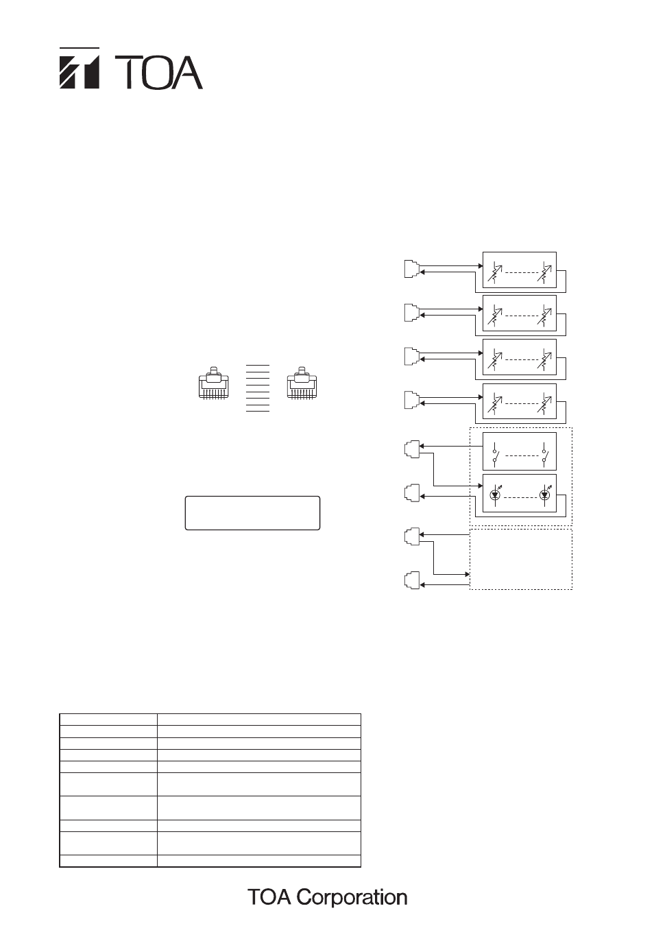
3. BLOCK DIAGRAM
VCA
IN CH 1-6
VCA
IN CH 7-12
VCA
OUT CH 1-4
VCA
OUT CH 5-8
CTRL
IN 1-4
CTRL
OUT 1-4
CTRL
IN 5-8
CTRL
OUT 5-8
1
6
DC
7
12
DC
1
4
DC
5
8
DC
DC
1
4
1
4
Make contact
5 – 8
Same as above
4. SPECIFICATIONS
• Accessories
Fader knob (Red, Yellow)* .............................. 3 each
Volume knob (Red)* ................................................ 2
Rack mounting screw 5 x 12 (with plane washer) ... 4
Rack mounting bracket (preinstalled on the unit) .... 2
* Convenient for color coding to distinguish
channels to which stereo link or group settings
are assigned.
Note
The design and specifications are subject to
change without notice for improvement.
Power Supply
5 V DC (supplied from the optional D-984VC)
Connector
RJ45 connector x 8
Input Fader Control
Input fader (100 mm) x 12
Output Volume Control Output volume control x 8
Contact Control
Illuminated switch x 8
Remote Output
No-voltage make contact output
(contact capacity: 30 V DC, 4 A)
Remote Switch
Seesaw switch for activating the remote function
of the power distributor
Finish
Panel: Pre-coated steel plate, black (30% glossy)
Dimensions
482.6 (w) x 177 (h) x 61.3 (d) mm
(excluding projection)
Weight
2.7 kg
1. GENERAL DESCRIPTION
The D-911 VCA Fader Unit is designed to remotely control
the digital mixer with the D-984VC VCA Control Module
installed. Connecting to the D-984VC permits volume
adjustment of input and output channels and contact
controls of the digital mixer.
2. HANDLING PRECAUTIONS
• Connect the D-911 to the
D-984VC VCA Control
Module installed in the
digital mixer. Connect each
of eight terminals to the D-
984VC's terminal of the
same name by way of the
fully-connected straight cable as shown on the right.
• Use the D-901 firmware of version 3.0 or later. Firmware
versions earlier than it cannot be used in conjunction with
the fader unit.
The firmware version
number can be confirmed
on the D-901's front
panel-mounted display.
If your firmware version is
old, download the latest software program and the "D901
PC software instruction manual" from the TOA Internet
product data site [http://www.toa-products.com/]. For the
update procedure, refer to the instruction manual.
• For channels with stereo link or group settings
established at the digital mixer, only the lowest numbered
channel in the preset link or group is enabled.
• Fader position "10" of the D-911 provides the channel
gain set by the digital mixer. As a guide, knob position 8
provides about 10 dB below the gain set by the D-901.
[Connection]
1
2
3
4
5
6
7
8
1
2
3
4
5
6
7
8
1 – 8
1 – 8
T O A D - 9 0 1 S e r i e s
S o f t w a r e V e r 3 . 0 0
[Display example]