Bs-301 manual_pg4_5 rev by tgi.pdf – Toa BS-301W AS User Manual
Page 4
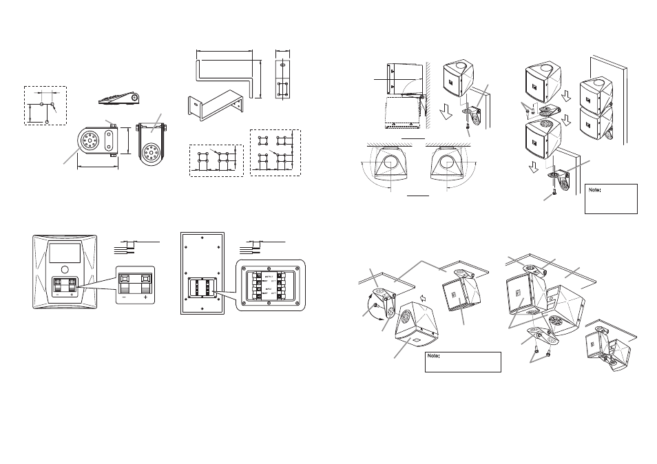
4.3. BRACKET (TO MOUNT SPEAKER)
4.3.1. BRACKET FOR SATELLITE SPEAKER
4.3.2.
BRACKET FOR SUBWOOFER
5. SPEAKER CABLE CONNECTIONS
5.1. SATELLITE SPEAKER
5.2. SUBWOOFER
6. INSTALLATION
6.1. SATELLITE SPEAKER
[Rear]
[Rear]
9mm
[0.35inch]
9mm
[0.35inch]
(Length of peeled cable)
(Length of peeled cable)
42
68
[Bottom]
[Top]
[Side]
Bracket-B
Bracket-A
Tightening Screw
55
15
5
222
[Side]
45
45
30
360
30
16-Ш9
38
7
30 360 30
45
8-Ш9
[Distance of the screw
holes on wall]
[Distance of the screw
holes on ceiling]
[Distance of the screw
holes on wall or ceiling]
32
3-Ø4.5
20
4
6.1.2.1 Installation on Wall
[single-system installation sample]
[double-system installation sample]
6.1.2.2 Installation on Ceiling
6.2. SUBWOOFER
Speaker unit
Speaker unit
5
0
o
(Horizontal)
90
o
90
o
(Turn to left)
90
o
(Turn to right)
(Top View)
(Side View)
0
o
(Vertical)
0
o
(Vertical)
M5x12 Screw
M5x12 Screw
M5x12 Screw
Speaker unit
Bracket
Bracket
Bracket
Note:
Red : + (positive)
Black : - (negative)
Mount bracket
to the wall
Mount bracket
to the wall
Mount bracket to
the ceiling
Mount bracket to
the ceiling
Ceiling
Ceiling
Note:
Screws to mount
the bracket onto the
wall are not provided
Note:
Screws to mount the bracket
onto the ceiling are not provided
Loosen the
tightening screw (right and left) to install
the bracket to the speaker unit. Take note of
Bracket-A; this is the part of the bracket which will be
attached to the wall or ceiling when installing the
speaker unit.
Place the speaker unit on an even and flat surface.
If the speaker unit is placed on glass or slippery surface, you may want to cover the surface with a cloth to prevent
the speaker from moving.
Before installing the bracket to speaker unit, remove / open the fixing seal enclosing the screw holes. Use a small
flathead screwdriver. Place the flathead screwdriver into the fixing seal slot (see image 4.1.). For installation of
single system, please remove only one fixing seal and for double system, please remove two fixing seals (top and
below) on one of the speaker units.
6.1.1.
Speaker Unit installation without bracket
6.1.2.
Speaker Unit installation with bracket
[Front]
[single-system installation sample]
[double-system installation sample]
M5x12 Screw
M5x12 Screw
Size : mm
The sound generated by the subwoofer may differ, depending upon the mounting position. The Subwoofer instal-
lation samples illustrated here are some of the appropriate positions for room installation. It is recommended to
place the subwoofer at the corner of the room for better sound (especially bass).