Bs-301 manual_pg3_6 rev by tgi (08aug09).pdf – Toa BS-301W AS User Manual
Page 3
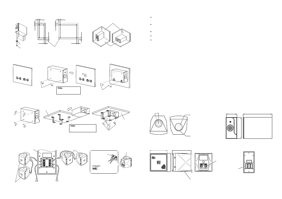
7. THE SPEAKER CABEL CONNECTIONS
50
40
50
50
50
40
50
50
6
Note:
Screws to mount the
bracket are not available
2. GENERAL DESCRIPTION
3. DESCRIPTION ON OVERLOAD PROTECTION
4. DIMENSIONAL DIAGRAM
4.1. SATELLITE SPEAKER
4.2. SUBWOOFER
2-M5 Screw holes (top and bottom)
(Screw length max. 12mm or 0.47inch)
92
100
1°
97
.5
22.5°
[Top]
[ Bottom]
[Rear]
[Rear]
Fixing seal
Note:
Find a big gap to open fixing seal.
Don't entering screwdriver too depth
(use its point)
Input Terminal
210
563
39
0
[Front]
[Side]
[Front]
[Side]
Input/Output
Terminal
Size : mm
3
Note:
Screws to mount the bracket
on ceiling are not available
RIGHT LEFT
LEFT
RIGHT
INPUT
OUTPUT
Speaker unit
Speaker unit
Subwoofer unit
To Amplifier
To Subwoofer
To Amplifier
Input Terminal Speaker
Speaker unit
[Rear]
Input Terminal
(Peeled cable)
9mm
To Speaker
The speaker system model BS-301 series is a speaker high-power with 2-way system that suitable for indoor
use only.
The wide range of frequency as well as capability of generating high sound pressure level make it an efficient
speaker to be used in a spacious room.
It is consisted of a subwoofer and four pieces satellite speakers.
he provided brackets allow the speaker to be mounted on various locations and direction radiations.
T
The mounting brackets come together with the product as accessories.
The speaker unit is equipped with an overload protector. The system shall protect the speaker unit from overload
input which exceeds the allowed capacity.
Speaker’s volume will turn lower if the input to the speaker exceeds the maximum capacity of the speaker.
In such event, please turn down the amplifier volume to the minimum level and wait for 10 seconds. The system
shall automatically reset to normal condition. You may then gradually re-adjust the amplifier volume to the level
lower then the previous volume.
Important Note!
The system does not entirely protect against overload. Prolonged overload input to the speaker unit will cause
the system to malfunction. As such, the overload input will flow in and damage the speaker unit.
It is important to prevent prolonged overload input exceeding the maximum limit from flowing into the speaker
unit.
Screw hole is enclosed by the
fixing seal from the factory.
Before mounting the bracket,
fixing seal shall be removed
first.
Please use a small flathead
screwdriver.
6.2.1. Installation on Floor
6.2.2. Installation on Wall
6.2.3. Installation on Ceiling
Use the rubber foot to install the subwoofer on the floor. Ensure the floor is even and flat so the subwoofer will
not move. Install the rubber foot on the side facing the floor.
For wall installation, unscrew two screws on the subwoofer. Take note of distance between the two screw holes
to be mounted on the wall (see image 4.3.2.)
For ceiling installation, please unscrew all screws (4 pieces) on the subwoofer. Take note of the distance
between the two screw holes to be mounted on the ceiling (see image 4.3.2.)
4-Rubber foot
Rubber foot
Floor
Wall angle
Vertical position
Horizontal position
4-Taping screws 3x14
Mount the bracket
on the wall
Unscrew 4 screws from
Subwoofer
Place the screws back
onto Subwoofer
Ceiling
Ceiling
Unscrew 2 screws
from subwoofer
Place the screws back
onto Subwoofer
(Turn)