Features, Input impedance change, Speaker installation – Toa BS-1120W User Manual
Page 2
2. FEATURES
• A built-in matching transformer permits the speaker to be
used for both high-impedance and low-impedance (BS-
1110W: 4
Ω, BS-1120W: 8 Ω) applications. The
impedance can be easily changed from outside the
speaker.
• Mountable to wall surfaces directly or using with supplied
or optional mounting brackets.
3. INPUT IMPEDANCE CHANGE
The speaker's impedance is factory-preset as follows.
BS-1110W: 100 V line, 10 W (1k
Ω) input
BS-1120W: 100 V line, 20 W (500
Ω) input
To change the impedance, use the rear-mounted slide
switch.
3.1. High Impedance (70 V or 100 V Line) Applications
Set the LINE switch to 70 V or 100V, and also the INPUT
switch to 10 W or 5 W you use. (The example below shows
the setting for 10 W on the 100 V line of the BS-1110W.)
In this case, use the speaker terminals HIGH and COM for
connection to an amplifier.
3.2. Low Impedance Applications
Set the LINE switch to the LOW position. (Shown below is
a setting example of the BS-1110W.)
In this case, use the speaker terminals 4
Ω and COM for
connection to an amplifier.
Notes
To avoid damage to the speaker, be sure to follow the
instructions below.
• Switch off the amplifier power when changing the input.
• Never connect the speaker to the amplifier's 70 V or 100
V line (high impedance) when setting the LINE switch to
the LOW position (4
Ω or 8 Ω).
LOW
OFF
LINE
100V
RATED INPUT 10W
INPUT
COM
HIGH
10W
5W
OFF
70V
4
LOW
OFF
LINE
100V
RATED INPUT 10W
INPUT
COM
HIGH
10W
5W
OFF
70V
4
4. SPEAKER INSTALLATION
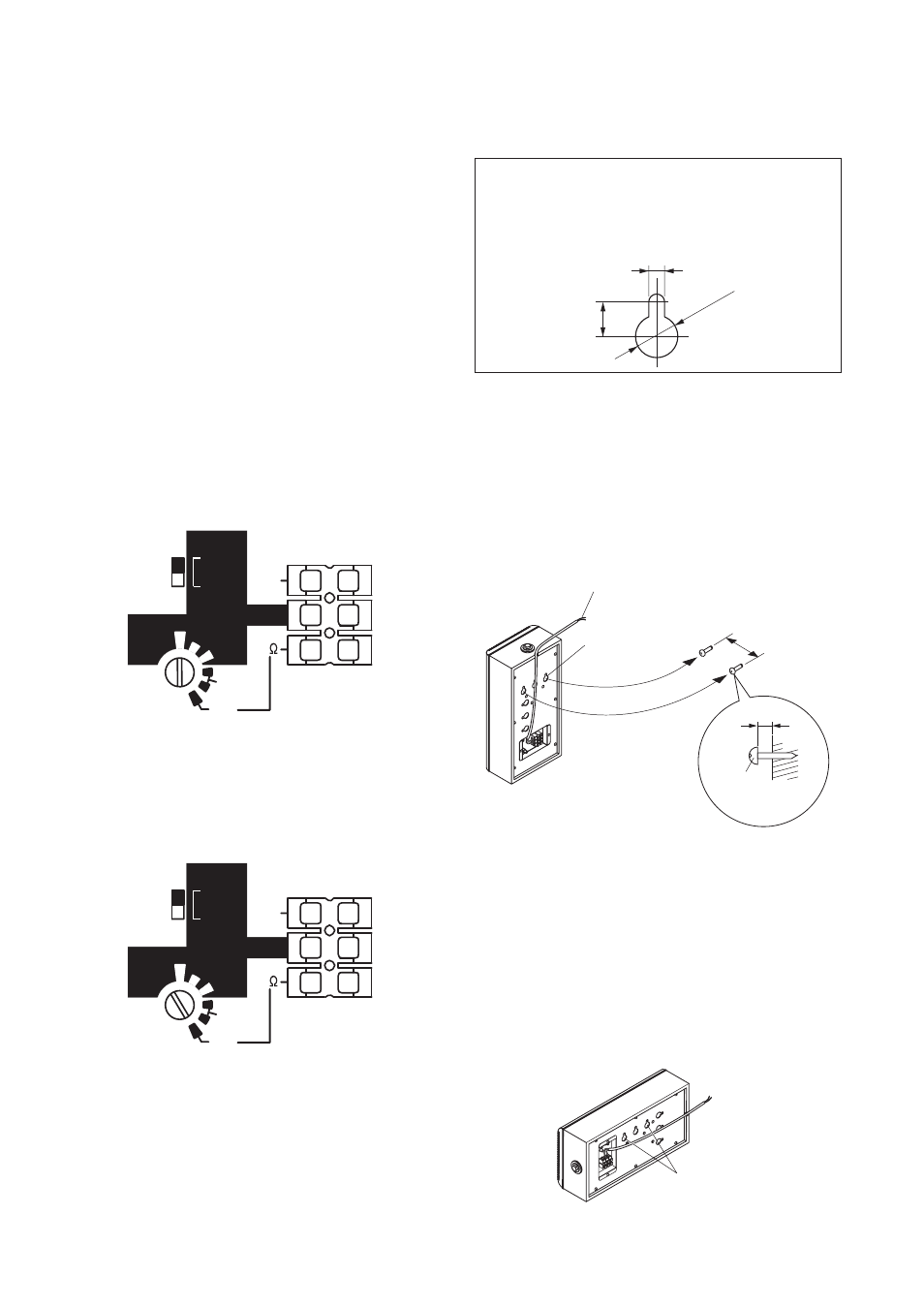
4.1. Wall Mounting – With Surface-Mount Screws
Note: The surface-mount screws are not supplied with
the unit. Referring to the mounting hole's dimensional
diagram below, prepare the screws appropriate to the
wall material.
6 mm
13 mm
ø16 mm
Step 1. Install 2 surface-mount screws in the wall 80 mm
apart and leave them sticking out approximately 10
– 12 mm from the wall surface.
Step 2. Connect the speaker cable.
Step 3. Place the speaker's rear panel mounting holes
over the 2 installed screws to mount the speaker to
the wall surface.
Note
Route the speaker cable as shown in the figure so that it is
not pinched between the speaker and the wall surface.
[When installing the BS-1110W horizontally]
Use the relevant mounting holes shown below. (BS-1110W only)
Note
As for the BS-1120W, never use the mounting holes for its
horizontal installaion.
1
2
3
Screw
(Please prepare
separately.)
Speaker cable
Mounting hole
10 – 12 mm
Wall
80 mm
Mounting hole