Detaching the speaker – Toa BS-1034S User Manual
Page 3
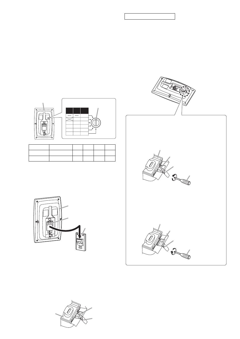
Impedance
500 Ω
1 kΩ
2 kΩ 3.3 kΩ 10 kΩ
100 V line
Never use this. 10 W
5 W
3 W
1 W
70 V line
10 W
5 W 2.5 W 1.5 W 0.5 W
6. DETACHING THE SPEAKER
Step 3. Hold and slide the speaker to insert its speaker
plug into the speaker receptacle.
Note
In this case, force the speaker onto the speaker
receptacle holding the speaker outer frame.
Step 4. Secure the speaker.
Turning the lock screw approximately about
3 counterclockwise turns using a Phillips
screwdriver causes the flap to rise up and stay
upright.
Caution
After speaker installation, be sure to make a
visual check that the flap rises to lock the
speaker completely.
Speaker receptacle
Speaker (Rear)
Speaker plug
Step 2. Change the input power (impedance) as
needed. (BS-1034 and BS-1034S only)
The input power (impedance) is factory-preset to
10 W (1 kΩ) for 100 V line.
When changing this setting, use a standard
screwdriver to turn the rotary switch on the
speaker's rear panel to the desired position.
Note
Be sure to follow the instructions below. Failure
to do so may cause damage to the speaker as
excessive input power is applied to it.
· Switch off the amplifier's power when changing
the input power.
· Never make 500 Ω connection in a 100V line
system, as excessive input power is applied to
the speaker, possibly resulting in damage.
Step 1. Turn the lock screw approximately 3 clockwise
turns.
The flap lies down and stays laid. (Refer to
"About lock mechanism.")
Step 2. Hold and slide the speaker to unplug it from the
speaker receptacle.
5W
10W
1W
3W
1.5W
0.5W
2.5W
5W
10W
3.3kΩ
10kΩ
2kΩ
1kΩ
500Ω
OFF
100V
LINE
70V
LINE
IMP.
Speaker (Rear)
Rotary switch
[When fixing the speaker]
[When detaching the speaker]
Lock screw
Phillips screwdriver
Speaker receptacle
Flap
Lock screw
Phillips screwdriver
Speaker receptacle
Flap
Turning the lock screw counterclockwise causes the
flap to rise up and move until it stops against the
other side of the recess.
Turning the lock screw clockwise causes the flap to
lie down and move until it stops against the front side
of the recess. (Factory preset position)
The lock mechanism is as shown below.
It prevents the speaker from being detached easily after
installation.
Note
Be sure to follow the instructions below. Failure to do so
may cause damage to the lock mechanism.
· Do not use an electric screwdriver when turning the
lock screw.
· Do not turn the lock screw more than the specified
turns.
About lock mechanism
Lock screw
Speaker receptacle
Flap