Speaker installation, Installation precautions, Wiring diagram 8. frequency response (1 w, 4 m) – Toa BS-1015BSW User Manual
Page 4: Vertical installation 6.2. horizontal installation
4
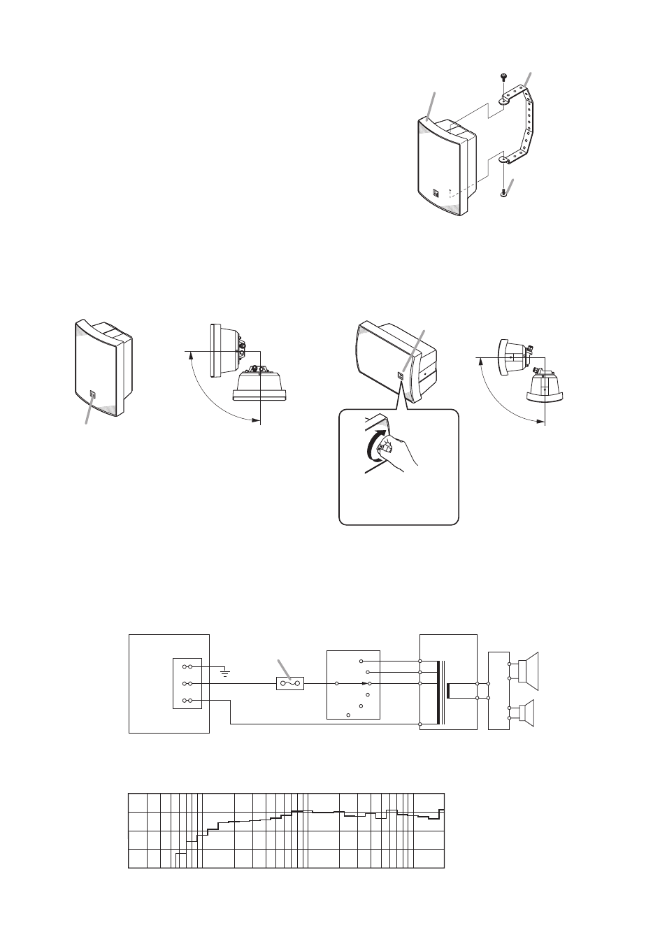
5. SPEAKER INSTALLATION
Step 1. Attach the bracket to the speaker using the supplied screws.
Step 2. Mount the speaker in the desired location using the
mounting holes made in the bracket.
Note: Bracket mounting hardware is not supplied with the unit.
Referring to the bracket's dimensional diagram, prepare the
correct type of screws or bolts appropriate to the wall material.
Bracket
(accessory)
Speaker
Machine screw with
washers M5 x 15
(accessory)
6. INSTALLATION PRECAUTIONS
Note: The splash-proof function required by the related Standards will not work with any other installation
method than those referred to below.
6.1. Vertical Installation
6.2. Horizontal Installation
Logo mark
Horizontal
Face-down
Install the speaker so that its front panel
orientation stays in the above range.
Horizontal
Face-down
Install the speaker so that its
front panel orientation stays
in the above range.
Logo mark
The logo mark can be
changed to correct its
orientation.
Note
Install the speaker so that the front panel logo is
positioned in the lower portion as shown above.
Note
Install the speaker so that the front panel logo is
positioned to the right side as viewed from the
speaker front.
8 Ω
1 kΩ
670 Ω
0
Matching
transformer
+
–
+
–
Network
COM
Rotary switch
2 kΩ
*
* Factory-preset
Earth
Screw terminal
HOT (+)
HOT (black)
COM (white)
COM (–)
Thermal fuse
(84 ºC or 183.2 ºF)
7. WIRING DIAGRAM
8. FREQUENCY RESPONSE (1 W, 4 m)
50
20
100
500
50
1 k
5 k
Frequency-SPL
10 k
20 k [Hz]
60
70
80
90
[dB]