Rear – Toa MP-1216 User Manual
Page 6
6
LINK
INDE.
MASTER
SLAVE
E
C
LINE
SP
16
15
14
13
H
–
+
E
C
H
–
+
E
C
H
–
+
E
C
H
–
+
E
C
LINE
SP
LINE
SP
LINE
SP
LINE
SP
LINE
SP
LINE
SP
LINE
SP
12
11
10
9
H
–
+
E
C
H
–
+
E
C
H
–
+
E
C
H
–
+
E
C
LINE
SP
8 7
6
5
H
–
+
E
C
H
–
+
E
C
H
–
+
E
C
H
–
+
E
C
LINE
SP
LINE
SP
LINE
SP
LINE
SP
LINE
SP
LINE
SP
LINE
SP
4
3
2
1
H
–
+
E
C
H
–
+
E
C
H
–
+
E
C
H
–
+
MULTI CHANNEL MONITOR model MP-1216
TOA Corporation MADE IN JAPAN
10
11
12
13
14 15
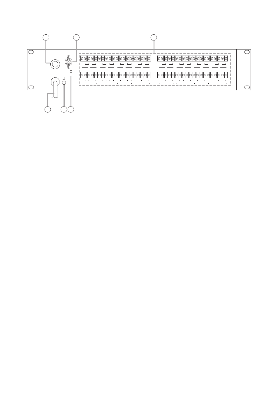
[Rear]
10. AC Fuse Holder
When replacing, be sure to use a fuse of the
same type and rating (see below) as the one
installed.
Fuse rating:
• 250 V 500 mA for MP-1216 US (120 V version)
• 250 V T250 mA for MP-1216 H and MP-1216
SA (220 – 240 V version)
11. Linkage Socket [LINK]
8P DIN socket.
Insert an optional linkage cable (YA-8) into this
socket when linking two MP-1216 units.
12. Input Terminals (1 – 16)
Connect a line signal to the LINE (H: Hot, C:
Cold, and E: Ground) terminals, and a speaker
signal (high or low impedance) to the SP (+, –)
terminals. Short-circuit between "C" and "E"
terminals using the supplied jumper strip when
the line signal to be input is of unbalanced type.
In this case, if loop hum noise occurs, remove
the jumper strip, then connect the line signal to
the "H" and "C" terminals. Be sure to replace the
unit's terminal cover after connection completion.
13. AC Power Cord
Plug the Power Cord into an AC outlet.
14. Functional earth terminal
Hum noise may be generated when external
equipment is connected to the unit. Connecting
this terminal to the functional earth terminal of
the external equipment may reduce the hum
noise.
Note: This terminal is not for protective earth.
15. Linkage Setting Switch
[INDE./MASTER/SLAVE]
Set this switch to INDE. position for a single unit
operation. When linking two units, set the switch
of one determined as "Master" unit to MASTER
position and that of one determined as "Slave"
unit to SLAVE position.