TeeJet FieldPilot 230 User Guide User Manual
Tilt compensation setup mode, Display setup mode
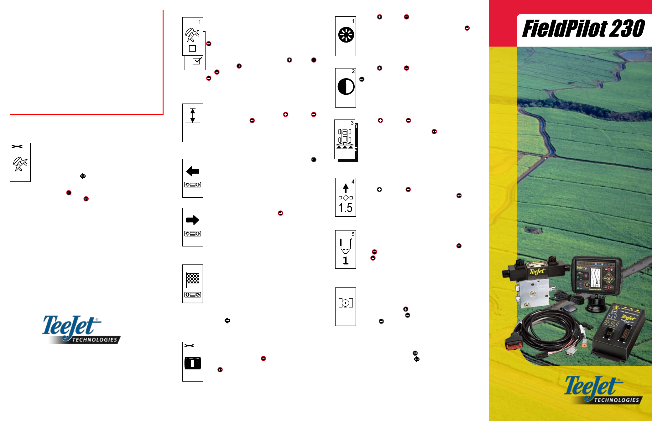
DISPLAY BRIGHTNESS
The Plus and Minus keys can be used to change the
brightness levels of the display screen. Press the keys until
the desired brightness is established. Press the Enter
key to advance to the Display Contrast setting.
DISPLAY CONTRAST
The Plus and Minus keys can be used to change the
contrast levels of the display’s background. Press the Enter
key to advance to the Display Background setting.
DISPLAY BACKGROUND
The Plus and Minus keys toggle between light and
dark backgrounds. Press the keys until the desired back-
ground is established. Press the Enter key to accept the
changes.
LED SPACING
The distance illustrated by the illuminated LEDs can be
customized. The default setting is 1.5 feet (.46 meters). Use
the Plus
and Minus
keys to adjust the spacing as
required for individual preference. Press the Enter key
to accept the changes.
COM PORT SETUP
The COM Port can be customized to send DGPS data out
or accept external DGPS. “0” means the console is accept-
ing external DGPS data. “1” means the console is using
internal DGPS and is transmitting out. Use the Plus and
Minus keys to toggle the COM Port number. Press the
Enter key to accept the changes. Power must be cycled
to the console if this setting is changed.
GPS SETUP
GPS Setup can be customized to accept “ANY” available
source transmission (either uncorrected or differential),
“GPS” source transmissions (only uncorrected signals), or
“DGPS” source transmissions (only differentially corrected
signals). Use the Plus key to select “ANY,” “GPS,” or
“DGPS” and the Minus key to revert backward. Press
the Enter
key to accept the changes. Power must be
cycled to the console if this setting is changed.
Once the final setting has been entered, the screen will return
to the initial Display Setup Mode screen. If no additional chang-
es are required, press the Escape key and exit to Opera-
tion Mode or press the Setup Mode key again to enter into
CL230BP Setup Mode.
NOTES:
When first tuning FieldPilot 230, refer to the Vehicle Kit installation instruc-
tions for the starting oil flow setting and any console settings that may be rec-
ommended for the particular vehicle. If no console settings are recommended
in the Vehicle Kit instructions, start with the default settings stated in this User
Guide and proceed as follows:
1. Use the Valve Test instructions to ensure that the valve is being driven in
the correct direction. If the vehicle steers in the reverse direction to the
setting selected on the console, swap the A and B valve connectors on
cable 45-10103 at the FieldPilot valve.
2. Adjust Valve Gain, Aggressiveness, and Sensitivity. Be aware that these
settings are interdependent. A large change in one of these settings may
require that adjustments are made in the other two settings.
3. Once Valve Gain, Aggressiveness, and Sensitivity have been properly
adjusted, proceed to fine-tuning the Look Ahead setting.
TILT COMPENSATION SETUP MODE
Tilt corrected GPS positions provide improved guidance per-
formance in hilly terrain. To provide accurate tilt correction, the
operator must calibrate the Steering Control Module (SCM). The
CL230BP will detect if an SCM is connected. If connected, tilt
calibration can be performed.
Press the Setup Mode
key until the initial Tilt Calibration
Setup Mode screen is displayed.
Press the Enter
key to save the setting and advance the
screen. Press the Escape key to exit from Setup Mode with-
out saving any changes. After 10 seconds of inactivity, Setup
Screens will time out (changes will be saved). The CL230BP will
return to Operation Mode.
1801 Business Park Drive
Springfield, Illinois 62703 USA
(217) 753-8424
www.teejet.com
TILT ON/OFF
A Tilt Correction On/Off page will be displayed. If the page
displays an empty checkbox, the Tilt Calibration screens
will not be available. If the box is checked, the Tilt Calibra-
tion screens will be accessed. If the box is checked and a
calibration has already been performed, press the Escape
key to avoid performing an additional calibration proce-
dure.
Check/Uncheck the box by using the Plus or Minus
keys. The Plus
key selects (checks) the box. The Mi-
nus key deselects (unchecks) the box. Press the Enter
key to accept the changes and advance to the Antenna
Height setting.
ANTENNA HEIGHT
Measure the height of the antenna from the ground. Enter
the antenna height (in feet and tenths of feet) (meters) on
the antenna height page using the Plus and Minus
keys. Press the Enter key to accept the changes and
advance to the Level One setting.
LEvEL ONE
Position the vehicle on a level surface. Press the Enter
key to advance to the next Level screen.
LEvEL TwO
Turn the vehicle 180 degrees and reposition the vehicle
at the same location. Press the Enter key to record the
level position.
FINAL TILT CALIBRATION SCREEN
The Final Tilt Calibration Screen will be displayed. This
will show that Tilt Calibration has been completed. After 5
seconds the screen will time out and return to the Opera-
tion screen.
DISPLAY SETUP MODE
Press the Setup Mode key until the initial Display Setup Mode screen
appears.
DISPLAY SETUP SCREEN
This is the initial Display Setup Screen. Setup screens
will time out after 10 seconds of inactivity (changes will be
saved). After time out, the screen will go back to Operation
Mode. Pressing the Escape key will also exit the user
from Setup Mode without saving any changes. Press the
Enter key to advance to the Display Brightness setting.
12.5
2
3
4
5
98-05137 R1
ANY