Design philosophy – Sutherland PhonoBlock User Manual
Page 5
DESIGN PHILOSOPHY
•
Third RC pi filter
•
Forth RC pi filter
•
Fifth RC pi filter
•
Constant voltage shunt regulator
•
Electrolytic and film capacitor bypass at the active devices
You can clearly see that each element adds ‘distance’ from the incoming AC power source. This is
also apparent when you look at the physical layout of components. Each element adds a physical
distance from the AC power connector. All listed items before the ribbon cable are in the right shielded
enclosure. They are in linear order from back to front. The ribbon cable goes from right to left, taking
power to the front of the audio board. Power filtering elements then go in linear order from front to back
on the audio board. Finally, you will see the electrolytic and film capacitors very closely clustered right
at the chips they are powering.
Simple, logical, straightforward, reliable AND effective.
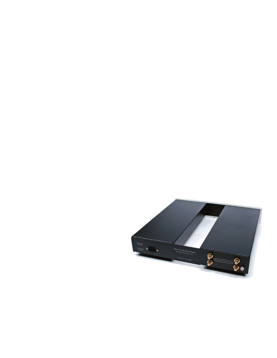
CASE / CONSTRUCTION:
Once a circuit topology is optimized for sound quality, it
is critical that the surrounding physical environment
is supportive of that achievement.
Like so many other aspects of the PhonoB-
lock design, the case is unassuming, classic
--------- but with a unique, purposeful twist.
There are two shielded enclosures behind
the machined front panel. The right side con-
tains the AC power supply and left side contains
the analog audio circuitry. We get the performance
advantages of shielded isolation and the tidiness of unification.
And yet there is another concealed advantage. Usually the cable interconnecting audio
and power supply sections is hanging out in space, exposed to radiated interference and other environ-
mental uncertainties. The PhonoBlock interconnection is hidden away, protected and totally shielded.
You don’t even see that cable. It is securely tucked into a machined channel in the aluminum front
panel.
There are other details making the PhonoBlocks special.