Sure Heat CVS303 LP Conversion User Manual
Page 3
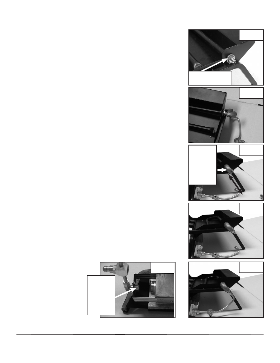
INFRARED BURNER LOG SETS
A. Remove the Natural Gas Orifice pre-installed in the Main Burner
and replace with the L.P. Air Shutter Orifice. This kit contains (2)
L.P Air Shutter Orifices, Part A and Part B. The orifice with the
small inner hole is used on the 18” Log Sets. The orifice with the
larger hole is used on 24” and 30” log sets. (See Figure 2)
B. Attach 3/8” Female Elbow (Part #19) to the L.P. Air Shutter Orifice.
Make sure the Elbow is angled in the same direction as the rear
grate leg. Next attach the 3/8 NPT x 1/8” Flare Adapter (Part C)
to the Elbow. (See Fig. 3, 4 & 5)
C. VERY CAREFULLY bend the aluminum tubing and connect to the
3/8” Flared Fitting. (See Fig. 6)
D. From the right hand back side of the Infrared Burner, Replace the
Natural gas Infrared Orifice with the L.P. Infrared Orifice.
(See Figure 7)
E. Replace the Natural Gas Pilot Burner Orifice with the
L.P./ Propane Orifice (Part D) supplied with this kit.
1. Remove Pilot Supply Line Nut (Part #14) from the Pilot Burner
(Part #7). Replace Natural Gas Orifice with the L.P. Gas Orifice
(Part D) included with this conversion kit.
NOTE: Refer to the detailed Safety Pilot Illustration on front
cover for placement of the L.P. Pilot Orifice.
F. Replace Heavy Media (Granules) supplied with the Natural Gas
Log set with Vermiculite Granules, sold separately. DO NOT USE
Heavy Media Granules as improper combustion will occur. After
the Vermiculite Bed has been put in place, spread the Glowing
Embers (insulation type material) supplied with the Gas Log Set
over the Vermiculite Bed.
RMH-130-00596B_Rev 1
08/08
Sure Heat Manufacturing • 1861 West Oak Parkway • Marietta, GA • 30062• 1-800-229-5647
Remove NG
Orifice
Elbow
at same
angle as
rear grate
leg
Infrared
Burner
Orifice
Fig. 3
Fig. 2
Fig. 4
Fig. 5
Fig. 6
Fig. 7