Sure Heat 2009 Surefire SF34LP User Manual
Page 9
9
9
B
A
Locate the side burner valve assembly out from underneath
1.
the control panel.
Using a Phillips screwdriver, remove the 2 screws from the
2.
side burner valve assembly. Set aside the screws.
Push the valve stem out through the opening in the front of
3.
the side burner shelf, lining up the threaded holes in the side
burner valve assembly with the openings on the side burner
shelf.
Position the side burner bezel (A) into place with the OFF
4.
position facing up, making sure to align the holes.
Attach the side burner bezel to side burner assembly face
5.
with screws removed in Step 2.
Press knob (B) onto valve assembly stem with OFF position
6.
facing up.
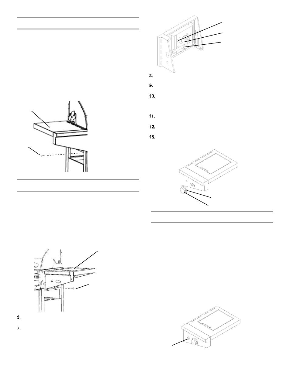
A. Igniter
A.
Large holding bracket
B.
Side burner casting
C. Small holding bracket
Assemble igniter assembly
Place the electronic igniter into the igniter hole on the front
1.
left of the side burner shelf. To help ease the installation of
the wires, make certain that the igniter wire tabs are facing
away from the grill.
Secure the igniter in place.
2.
Install “AA” battery, negative end (-) first.
3.
Install spring and cap assembly and tighten securely.
4.
Attach loose wire to bottom of IR burner, and then to any
5.
of the open tabs in the igniter. Insert the 6 igniter wires, fed
through the grommeted hole on side of grill cart in Step
2 of the “Assemble Side Burner Shelf” section, into the
remaining 2 holes.
NOTE: The igniter is designed in such a way that it does
not matter which terminal tab is used when connecting
igniter wires.
Feed the side burner gas supply hose assembly through the
1.
hole in the side of the cart.
Loosen four bolts on the right of the grill head assembly by
2.
approximately 1/4”.
Press the side burner shelf against the grill and press
3.
downward until the shelf locks in place. Make sure the top
trim strip is hanging all the way inside of the grill before
pressing downward.
Install 1 self-tapping screw into the bottom front hole under
4.
the shelf.
Secure the four bolts on the right of the grill head assembly.
5.
A. Side burner shelf
B. Self-tapping screw
Assemble side burner assembly
A
B
C
A
A
B
A. Bezel
B. Knob
Secure the large holding bracket (A) on the side burner
1.
assembly with two (2) self-tapping screws.
Insert the side burner casting (B) into the holding bracket of
2.
the side burner assembly with two (2) self-tapping screws.
Then secure the small holding bracket (C) with two (2) self-
tapping screws.
6.
7.
8.
9.
10.
11.
12.
13.
A. Side shelf
B. Self-tapping screw
Lay the side shelf left assembly on its side.
1.
NOTE: Be
careful not to scratch the sides of the shelf.
Place a piece of styrofoam from the packaging inside the
2.
roll top hood propped open slightly.
Loosen four bolts on the left of the grill head assembly by
3.
approximately 1/4”.
Press the shelf against the grill and press downward
4.
until the shelf locks in place. Make sure the top trim strip
is hanging all the way inside of the grill before pressing
downward.
Install 1 self-tapping screw into the bottom front hole under
5.
the shelf.
Secure the four bolts on the left of the grill head assembly.
6.
Assemble side shelf
A
B