Rear p anel connections - master j a cks – Studio Projects SP828 User Manual
Page 4
7
6
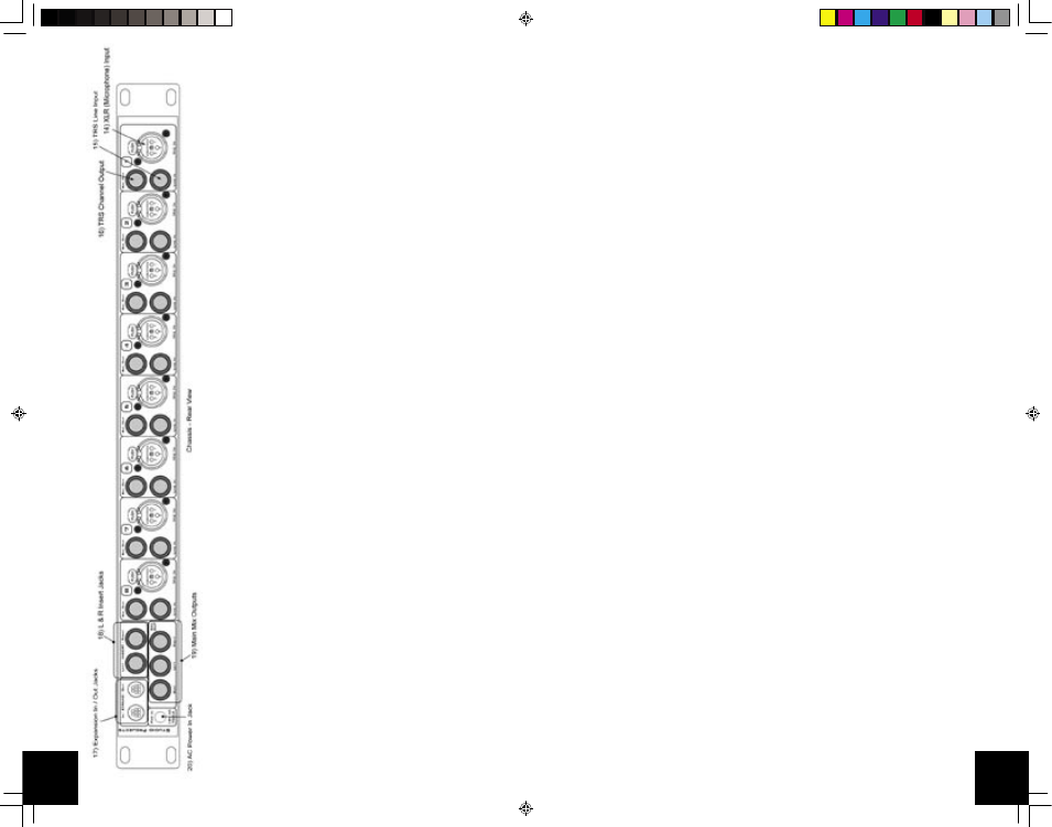
REAR
P
ANEL
CONNECTIONS
-
INDIVIDU
AL
CHANNEL
J
A
CKS
14)
XLR
Input
J
ac
k
This
3-Pin
Female
XLR
jack
is
used
to
bring
balanced
signals
into
the
channel.
Normally
,
microphones
are
connected
to
this
jack,
and
are
selected
by
having
the
front-panel
Line
switch
in
the
UP
position,
but
hi-level
signals
can
be
accommodated
by
pressing
the
front-panel
Line
switch
(#6).
Input
imped
-
ance
is
approx
3K
ohms.
15)
Line
Input
J
ac
k
This
1/4”
TRS
jack
is
used
to
bring
line-level
balanced
or
unbalanced
signals
into
the
channel.
This
jack
is
selected
with
the
front-panel
Line
switch
(#6).
If
nothing
is
plugged
into
this
jack,
the
XLR
signals
are
normalled
into
the
TRS
circuit
which
allows
the
front-panel
Line
switch
to
do
double-duty
as
a
P
AD
switch.
Input
impedance
is
approx
15K
ohms,
so
Hi-impedance
instruments
(guitars,
bass)
should
not
be
plugged
in
here.
No
damage
will
occur
,
but
the
sound
will
not
be
optimum
for
those
instruments.
Use
an
outboard
preamp
or
buf
fer
amplifier
for
these
types
of
instruments.
16)
Channel
Output
This 1/4”
TRS jack is used for the channel output. Signals from the channel can be fed into individual tracks for recording. Nominal output level is +4dBu.
Output impedance is 100 ohms, ground-compensated, impedance balanced.
This allows this jack to be connected to balanced and unbalanced inputs
without concern. Use a balanced (2-wire w/shield) cable for all connections for best results.
REAR
P
ANEL
CONNECTIONS
-
MASTER
J
A
CKS
17)
Expansion
In
/
Out
jac
ks
These
8-Pin
mini-DIN
jacks
are
used
to
tie
SP-828
units
together
.
When
connected,
the
“Slave”
SP-828
will
send
its
signals
to
the
“Master”
SP-828.
L/R
mix
and
Solo
signal
and
control
signals
are
sent
out
of
the
Expansion
Out
jack
of
the
“Slave”
SP-828,
and
are
received
on
the
Expansion
In
jack
of
the
“Master”
SP-828.
By
chaining
additional
units
together
,
up
to
32
channels
(4
units)
can
be
mixed
together
and
monitored
from
one
master
unit.
The
mini-
DIN
connector
cables
should
be
shielded
and
wired
Pin-to-Pin
and
limited
to
3
feet
in
length
for
best
results.
18)
L/R
Inser
t
J
ac
ks
The
1/4”
TRS
jacks
are
used
to
insert
processing
gear
into
the
L/R
mix.
Stereo
compressors
or
EQs
are
typically
used
here.
The
insert
point
is
located
after
the
mix
amp
and
before
the
main
level
control.
T
ip
is
Send,
Ring
is
Return,
Sleeve
is
audio
ground.
Send
impedance
is
100
ohms,
return
impedance
is
10K
ohms.
19)
Main
Output
J
ac
ks
These 1/4”
TRS jacks are the main mixed outputs of the unit.
The L/R outputs are available here as well as a summed-mono mix of the L
& R outputs.
The overall level is controlled by the front-panel L/R level control (#1
1). Nominal output level is +4dBu. Output impedance is 100 ohms, ground-compen
-
sated, impedance balanced.
This allows this jack to be connected to balanced and unbalanced inputs without concern. Use a balanced (2-wire w/shield)
cable for all connections for best results.
20)
A
C
P
o
w
er
In
jac
k
This 5.5mm barrel jack brings low-voltage
AC power into the unit. 18 volts at 750mA
is required for proper operation. Only use the supplied
AC adaptor
from Studio Projects.
sp828 manual.indd
2/22/05, 11:06 AM
8-9