Jumper settings, Rs232 pinout, Jumper settings rs232 pinout – StarTech.com PEX2S553S User Manual
Page 5
Instruction Manual
2
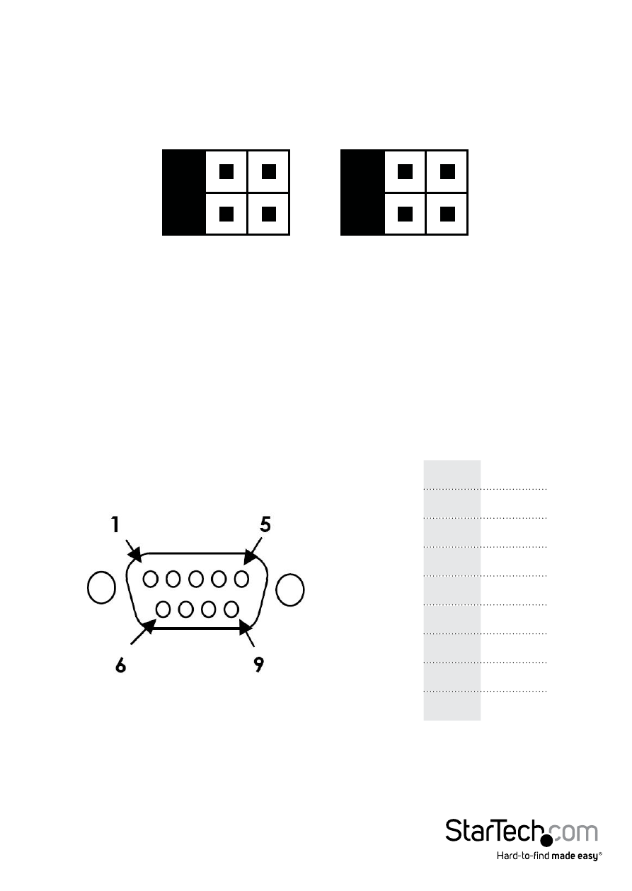
Jumper Settings
Power over serial Enable/Disable (per-port):
Each port has 2 sets of jumper pins (labeled above) that can be configured to provide
power over Pin 1 and/or Pin 9, or neither.
RS232 Pinout
NOTE: Pin 1 and/or 9 of the DB9 connector will output DC power if the corresponding
jumper was enabled.
DCD (Data Carrier Detect): No power
sent over Pin 1
5V: DC5V, from LP4 (LP4 power
connection required)
12V: DC12V, from LP4 (LP4 power
connection required)
RI (Ring Indicator): No power sent over
Pin 9
5V: DC5V, from LP4 (LP4 power
connection required)
12V: DC12V, from LP4 (LP4 power
connection required)
Pin 1
DCD
Pin 2
RXD
Pin 3
TXD
Pin 4
DTR
Pin 5
GND
Pin 6
DSR
Pin 7
RTS
Pin 8
CTS
Pin 9
RI
Pin 1
Pin 9
DCD 5V
12V
RI
5V
12V
See also other documents in the category StarTech.com Hardware:
- INFOSAFE IDE2510U2 (12 pages)
- IDE3510U2GB (11 pages)
- IDE3510U2GB (11 pages)
- PEXSATA22I (12 pages)
- PCI1394B_3 (8 pages)
- CARDBUS CB420USB (9 pages)
- PCI EXPRESS SERIAL ADAPTER PEX4S952 (8 pages)
- ICUSB422 (10 pages)
- ICUSB422 (9 pages)
- MADE EASY HSB110SATBK (2 pages)
- PCI8S9503V (13 pages)
- PCI8S9503V (14 pages)
- P-Touch 9500PC (4 pages)
- EC1000S (9 pages)
- SATSAS225ODD (2 pages)
- SATSAS225ODD (2 pages)
- SAT2510BU2B (10 pages)
- PCI4S650PW (12 pages)
- ST100SLP (10 pages)
- PEXUSB400 (9 pages)
- PCISOUND4LP (10 pages)
- STARVIEW SV441DUSBI (52 pages)
- SAT2510BU2E (12 pages)
- SAT2510BU2E (12 pages)
- PCISOUND4CH (10 pages)
- PEX2EC35 (11 pages)
- PCISOUND5CH (10 pages)
- PCI EXPANSION BAY PEX2PCI4 (13 pages)
- PEX1P (9 pages)
- PCI EXPRESS PEXSATA24E (11 pages)
- HSB220SAT25B (11 pages)
- CTK400LAN (9 pages)
- HSB100SATBK (9 pages)
- CE IDE HARD ENCLOSURE IDE1810U2Z (10 pages)
- ST1000BT32 (11 pages)
- SV211KDVI (10 pages)
- SV211KDVI (10 pages)
- PCI EXPRESS 10/100 PEX100S (11 pages)
- SAT32MSAT257 (9 pages)
- SAT2IDEADP (11 pages)
- SAT32M225 (11 pages)
- S322SAT3R (14 pages)
- IDE2SAT (2 pages)
- 25SAT22MSAT (13 pages)
- SAT2MSAT25 (11 pages)