Installation, Wall-mounting, Hardware installation – StarTech.com IES51000POE User Manual
Page 6: Wall-mounting hardware installation
Instruction Manual
3
Installation
Wall-Mounting
The Network Switch is designed to sit on a flat surface (such as a desktop) or mount to
a wall or similar surface. Skip to the Hardware Installation section below if you are not
wall-mounting the device.
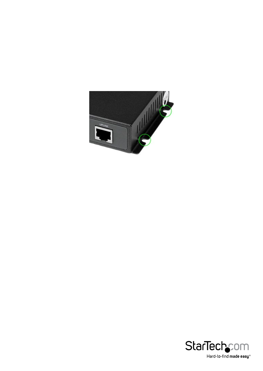
1. Determine the desired location and orientation of the switch on the wall, and mark
both mounting notch location on one side of the integrated mounting bracket,
ensuring they are level.
2. Depending on the mounting surface, use the appropriate tools to install the
included screws into the wall, leaving a gap of approximately 2 mm between the
head of the screw and the wall surface.
3. Place switch back onto the wall with the mounting notches against the previously
installed screws and mark the location for the mounting notches on the opposite
side of the device.
4. With the switch in place on the wall, install the remaining two screws on the other
side so the device is held in place.
Hardware Installation
1. Plug one end of the power adapter into an open electrical outlet and plug the other
end into the DC connector on the side panel of the Network Switch. The Power LED
on the front of the Switch should now be lit.
2. Connect a network cable to the Uplink port on the front panel of the switch, and
connect the other end of the cable into the RJ-45 port on your upstream switch or
router. The Uplink connection speed should auto-detect and the appropriate LEDs
will illuminate to show activity.
3. Connect your PoE or non-PoE devices to the remaining 4 ports on the rear panel
of the switch (e.g. computer, IP Phone, IP Camera, etc.). The switch will auto-detect
connection speed and whether PoE is required, and the appropriate LEDs will
illuminate and show activity.