StarTech.com 4POSTRACK12A User Manual
Instruction manual, Packaging contents, Tools required
Instruction Manual
DE: Bedienungsanleitung - de.startech.com
FR: Guide de l'utilisateur - fr.startech.com
ES: Guía del usuario - es.startech.com
IT: Guida per l'uso - it.startech.com
NL: Gebruiksaanwijzing - nl.startech.com
PT: Guia do usuário - pt.startech.com
Manual Revision: 04/24/2013
For the most up-to-date information, please visit: www.startech.com
Packaging Contents
• 2 x Front/Rear Frame
• 4 x Horizontal Frame Posts
• 2 x Adjustable Vertical Post
• 52 x Hex bolt and Washer
• 16 x KEP nut
• 16 x M6 Cage Nut and Cabinet Screw
• 4 x Swivel Caster
Tools Required
• Adjustable wrench
4POSTRACK12A
12U 4 Post Server Equipment Open Rack Cabinet /w Casters
Installation
Verify packaging contents before proceeding with assembly.
1. Stand the Front Frame piece upright so that the square holes run
from top to bottom (the Front Frame piece is labeled with the
StarTech.com logo in the top corner).
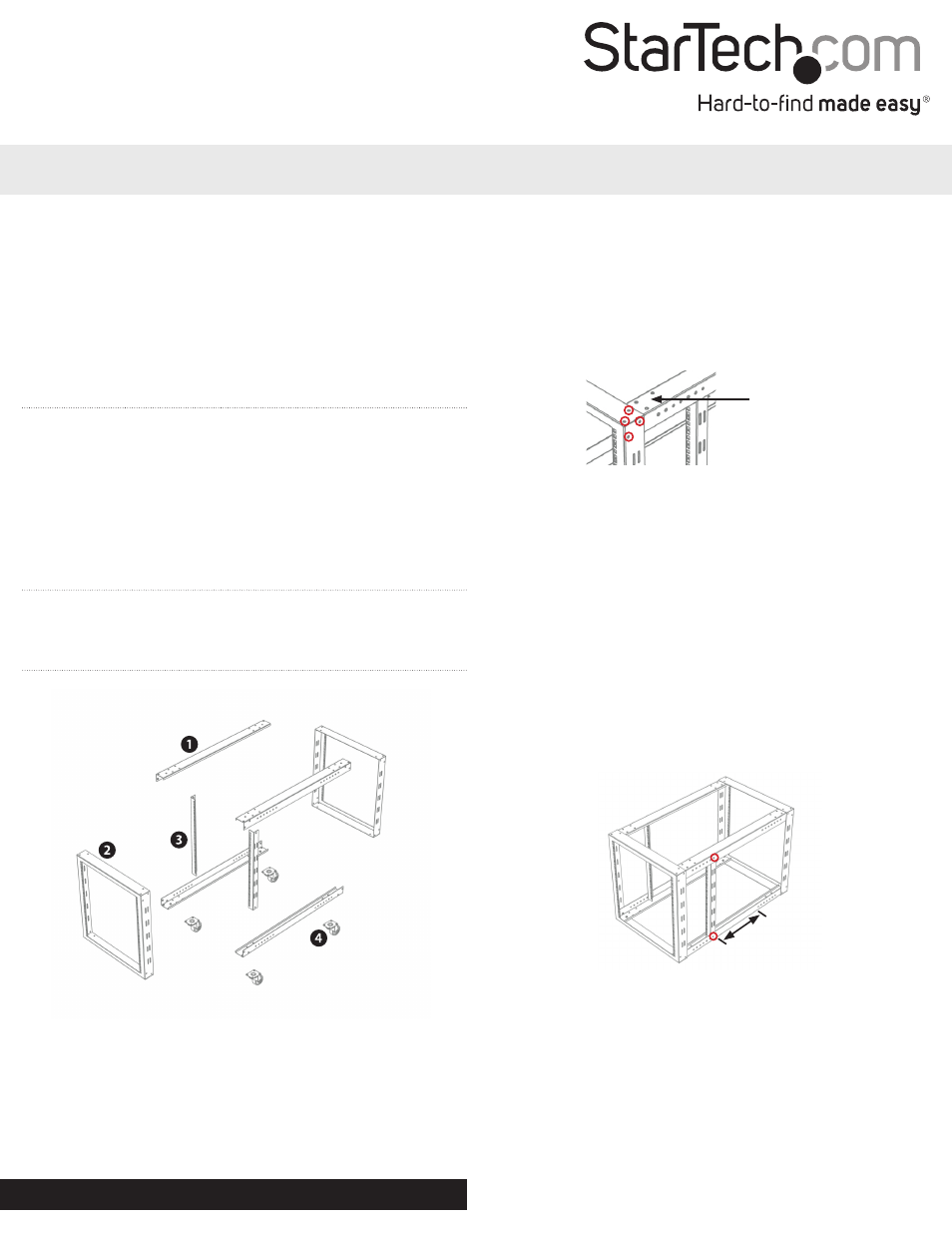
2. Place one of the Horizontal Frame Posts along the top inside
corner of the Front Frame piece with the Caster mounting holes
facing upwards, and line up the screw holes of the Front Frame
with the holes of the Horizontal Frame Post.
3. Fasten the two pieces together by threading the provided hex
bolts (4), with washers (4) into the pre-welded nuts from the
outside of the frame.
NOTE: In order to ensure all of the screw holes will line up easily,
it is recommended to hand-tighten the nuts through the entire
assembly process, and then tighten using an adjustable wrench
once all bolts have been inserted.
4. Set up the Rear Frame piece at the other end of the Horizontal
Frame Post and fasten by threading the provided hex bolts (4)
with washers (4) into the pre-welded nuts from the outside
of the frame.
5. Repeat step 2-4 to attach the remaining Horizontal Frame Posts
to the remaining 3 corners, turning the rack over to attach the
bottom Horizontal Frame Posts.
6. The 2 Adjustable Vertical Posts can now be attached to the top
and bottom Horizontal Frame Posts. The mounting depth of the
vertical posts can be adjusted in 1” increments. Ensure both posts
are installed at the same positions.
NOTE: There is a 15” section in the center of the Horizontal Frame
Posts where the Adjustable Vertical Posts cannot be attached
(marked in the diagram). They can be mounted up to 11” from the
front or rear of the rack.
7. On the bottom two horizontal frame posts there will be 4 holes
located at both ends. The casters can be fitted here and fastened
using the supplied Hex bolts and KEP nuts.
8. To mount rack-mountable equipment into the rack, determine
the appropriate height on the rack and match with the mounting
points on your equipment mounting brackets.
9. Place the square cage nuts into the appropriate square mounting
holes (from the inside).
10. Mount your equipment into the rack and fasten to the cage nuts
with the appropriate cabinet screws.
1. Horizontal Frame Post
2. Front/Rear Frame
3. Adjustable Vertical Post
4. Casters
Caster
Mounting Holes