Cabletron Systems MicroMMAC 24T MICROMMAC- User Manual
Page 44
INSTALLATION
3-9
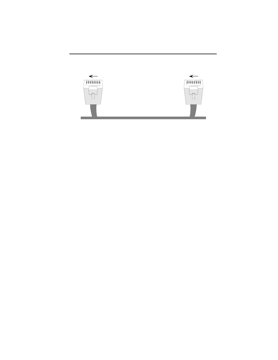
RJ45 Plug
to
RJ45 Plug
(at TCU)
(at device port)
Pin 3 (Receive -) . . . . . . . . . to. . . . Pin 3 (Transmit -)
Pin 4 (Transmit +) . . . . . . . . to. . . . Pin 4 (Receive +)
Pin 5 (Transmit -). . . . . . . . . to. . . . Pin 5 (Receive -)
Pin 6 (Receive +) . . . . . . . . . to. . . . Pin 6 (Transmit +)
Figure 3-9. Network lobe pinouts
Figure 3-10 and Figure 3-11 illustrate possible MicroMMAC-T cabling
configurations.
1
8
RJ45 Plug
1
8
RJ45 Plug
This manual is related to the following products: