SmarTek Systems SAS-1 Relay Interface Configuration And Connection User Manual
Page 7
SmarTek Systems (www.smarteksys.com)
7
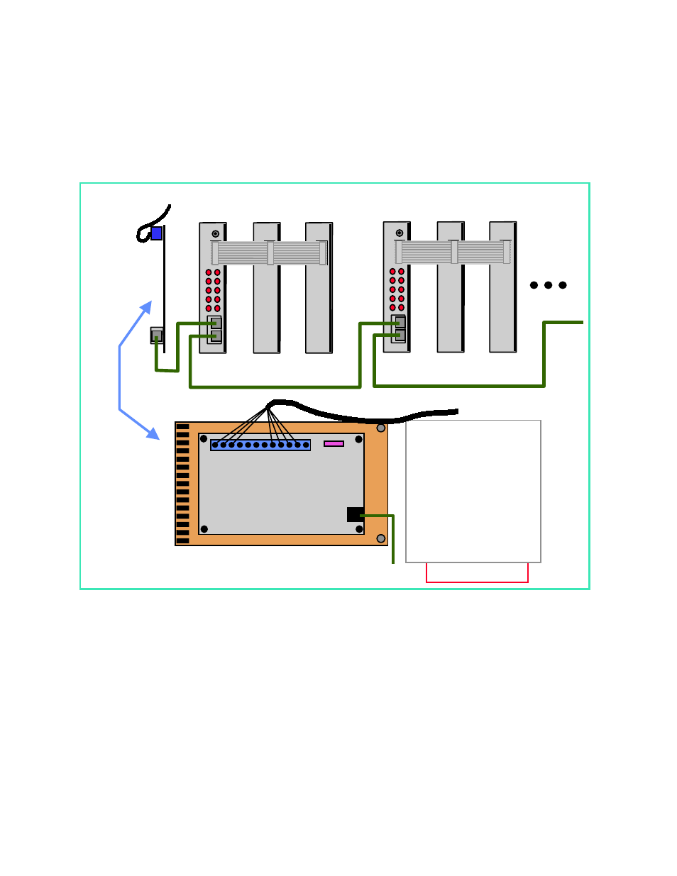
on the second SAS-RI to the RJA jack on the third SAS-RI. This pattern continues for up to 6
SAS-RI cards.
Note:
Each SAS-RI used as slaves (SAS0002 thru SAS0006) in Figure 6 must be factory
modified for receive only capability. They are not interchangable with the SAS-RI used as the
Master (corresponding to SAS0001).
Figure 7 shows the cabling for multiple shelf mount SAS-RIs connected to a single SAS-CT.
The cable used for the interconnects is standard straight thru CAT 5E cable with RJ-45
connectors on both ends. The cable is connected from the RJ-45 jack on the SAS-CT to the RJA
jack on the first SAS-RI (Master corresponding to SAS0001). The next cable is routed from the
RJB jack on the first SAS-RI to the RJA jack on the second SAS-RI. The next cable is routed
from the RJB jack on the second SAS-RI to the RJA jack on the third SAS-RI. This pattern
continues for up to 6 SAS-RI shelf mount units.
Data/Power Cable(s)
From SAS-1(s)
K
K+3
K+2
RJA
RJB
For
SAS0001
D 1
D 2
Card File Slot
SAS-CT
L
L+3
L+2
RJA
RJB
For
SAS0002
D 1
D 2
Card File Slot
SAS-CT To SAS-RI (RJA) Cable
(For Operation)
Data/Power Cable(s)
From SAS-1(s)
+
-
1
12
SAS Cabinet Termination
DC IN
Fuse
Power 8 to 24 VDC
1 NC
2
Blue
TxD+ (In)
3 Blk of Blu TxD- (In)
4
Green
RxD+ (Out)
5 Blk of Grn RxD- (Out)
6 NC
7 NC
8 NC
9 NC
10 Blk of Red GND
11
Red
VDC (Out)
12 Shield GND
Figure 6 Connecting Multiple Type 170 SAS-RI Cards to a Single SAS-CT