SmarTek Systems SAS-1 Relay Interface Configuration And Connection User Manual
Page 5
SmarTek Systems (www.smarteksys.com)
5
a card edge contact (F, W, S, Y). From Figure 4 it can be seen that the SAS-RI Main card routes
relay signals 1A, 1B, 2A, and 2B to four card edge contacts. The SAS-RI Daughter Card 1
routes relays signals 3A, 3B, 4A, and 4B to four card edge contacts. And finally, the SAS-RI
Daughter Card 2 routes relay signal 5A and 5B to two card edge contacts. For Type 170 card
files, contacts S and Y are routed to contacts F and W respectively in the adjacent lower
numbered slot (i.e. contacts S and Y in slot 2 are routed to F and W in slot 1). Plug each SAS-
RI Card into the appropriate slots in the Type 170 card file to avoid relay signal conflict (Figure
3). Note the use of slot K+3 instead of slot K+4 for SAS-RI Daughter Card 2. Since SAS-RI
Daughter Card 2 routes only two relay signals to card edge contacts F and W, slot K+3 can be
used without conflict. For the jumper configuration shown in figure 4, the relay signals are
routed to the following Type 170 Card File positions:
Signals 1A and 1B
to
Slot K-1, contacts F and W
Signals 2A and 2B
to
Slot K, contacts F and W
Signals 3A and 3B
to
Slot K+1, contacts F and W
Signals 4A and 4B
to
Slot K+2, contacts F and W
Signals 5A and 5B
to
Slot K+3, contacts F and W.
Connecting SAS-RIs For Up To Six SAS-1 Units
For a single SAS-1 connected to the home run cable and the SAS-CT, remove all jumpers from
the JP2 Header on the SAS-RI. Make sure that the SAS-1 Default Operating Mode is setup for
either Single Relay or Dual Loop Relay Mode and Periodic communication.
Connect the ribbon cable to
each header on the main SAS-
RI card and on each of the
daughter cards as shown in
Figure 3. This ribbon cable is
used to distribute all ten relay
signals from the SAS-RI Main
Card to each of the Daughter
Cards. If the shelf mount SAS-
RI is being used, make sure that
the relay and power conductors
are securely connected to the
correct terminal (Figure 2).
Connect the serial cable
(straight thru Cat 5E) to the
SAS-CT (RJ-45) and to the
SAS-RI Main Card (RJ-45
receptacle marked RJA).
Apply power to the card file (or the shelf mount SAS-RI) and to the SAS-1 unit (SAS-CT). The
system should now be operating. Observe the Activity LED (inside on the Type 170 SAS-RI
card or on the back of the shelf mount SAS-RI) and the detection indicator LEDs to verify proper
operation. The activity LED should blink with a nearly constant period. The detection LEDs
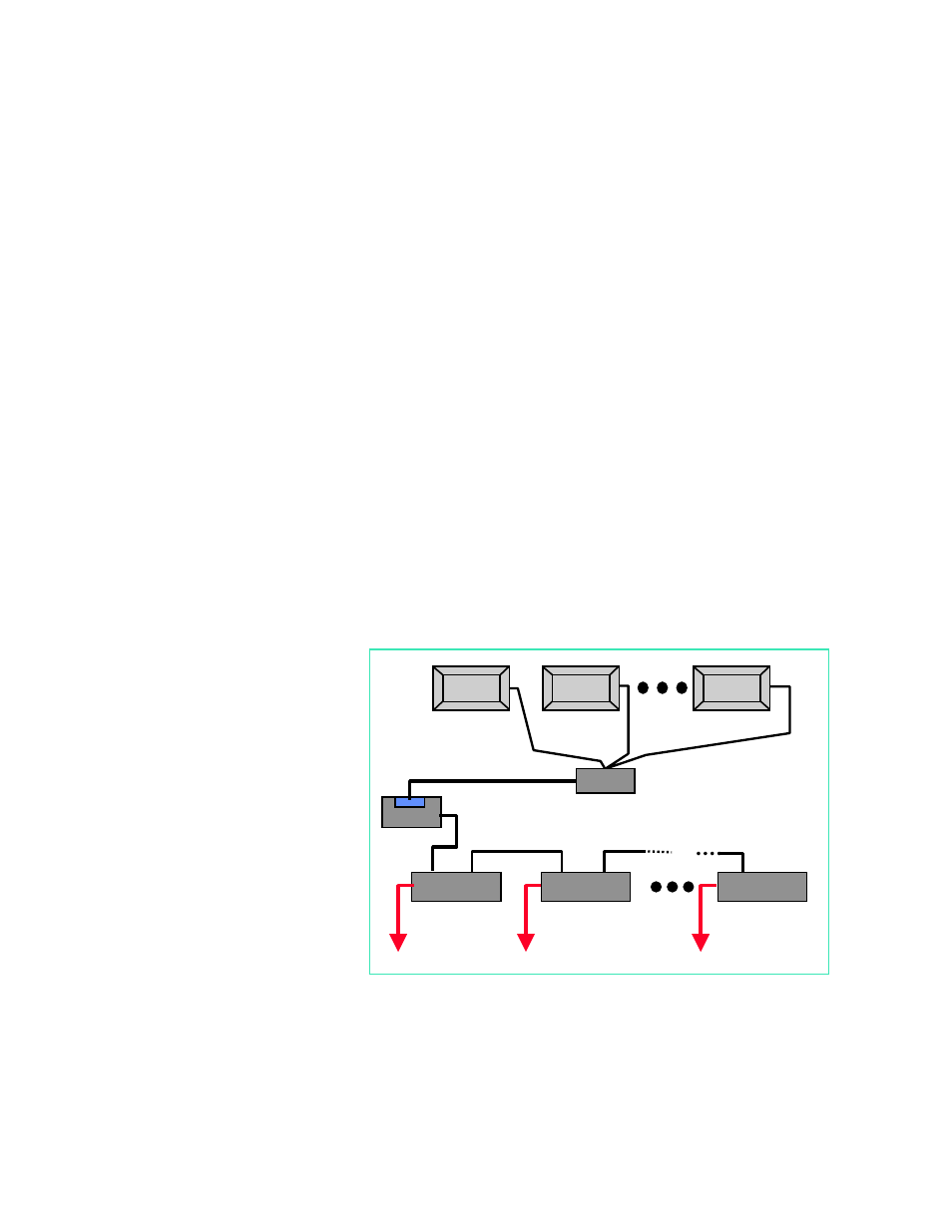
Figure 5 Connecting Multiple SAS-1s and SAS-RIs
SAS-CT
SAS-RI
(SAS0001)
SAS-RI
(SAS0002)
SAS-RI
(SAS0006)
(SAS0001)
(SAS0002)
(SAS0006)
Relay Signals to Cabinet Controller
RJA
RJB
RJA
RJB
SAS-JB
RJA
Multiple SAS-1s can share a home run cable or come
together at the SAS-CT