SkyHunter406 4000-10 AP User Manual
Page 7
3.3
ELT INSTALLATION DETAILS - FIXED-WING AIRCRAFT
3.3-1
Attach mounting bracket to the aircraft structure so that, when the unit is installed, the "DIRECTION OF FLIGHT"
arrow on the ELT control face points forward in the direction of flight. Drill four holes and attach the mounting
bracket with # 6 pan head screws.
All attaching hardware must be of material and type suitable for Aircraft
application. Heads must be flush with bracket surface.
3.3-2
Figure 3 shows a typical fixed-wing aircraft installation. Insert transmitter into the mounting bracket and position
bracket strap forward of rear telescopic antenna clip and over the unit case. Open latch, attach to clip and lock into
place.
3.3-3
Place the Master Switch in the "AUTO" position and install Master Switch Guard clip.
3.3-4
Record the installation in Aircraft Logbooks.
3.3-5
A remote whip antenna and coaxial cable are provided with model 4000-10 for external mounting. See
Section 3.5 for antenna mounting details.
3.3-6
EXTERNAL MARKING. An "
ELT LOCATED HERE" decal is supplied with each system, to indicate
transmitter location.
3.4
INSTALLATION DETAILS - ROTARY-WING (HELICOPTER)
3.4-1
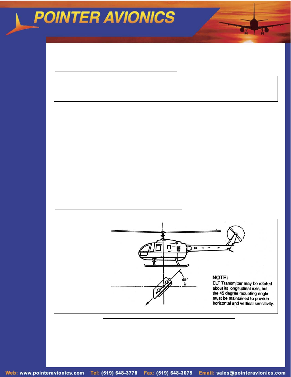
All mounting instructions are identical to Fixed-Wing with the exception of the mounting angle as shown in Fig. 4.
FIGURE 4. MOUNTING POINTER ELT IN ROTARY-WING AIRCRAFT
NOTE:
Prior to installing the ELT transmitter, check that battery replacement date is
marked in the space on the label at the end of the unit.
Mounting Instructions
are identical to fixed
wing A/C (ref Fig.3)
HORIZONTAL