Installation check-out and adjustments, Page 3, Figure 4 – Sigtronics Sport 200 S Installation Instructions (Out of Production) User Manual
Page 3: Table 1 - p1/j1 - see wiring instructions, Table 2 - p2/j2 - see wiring instructions
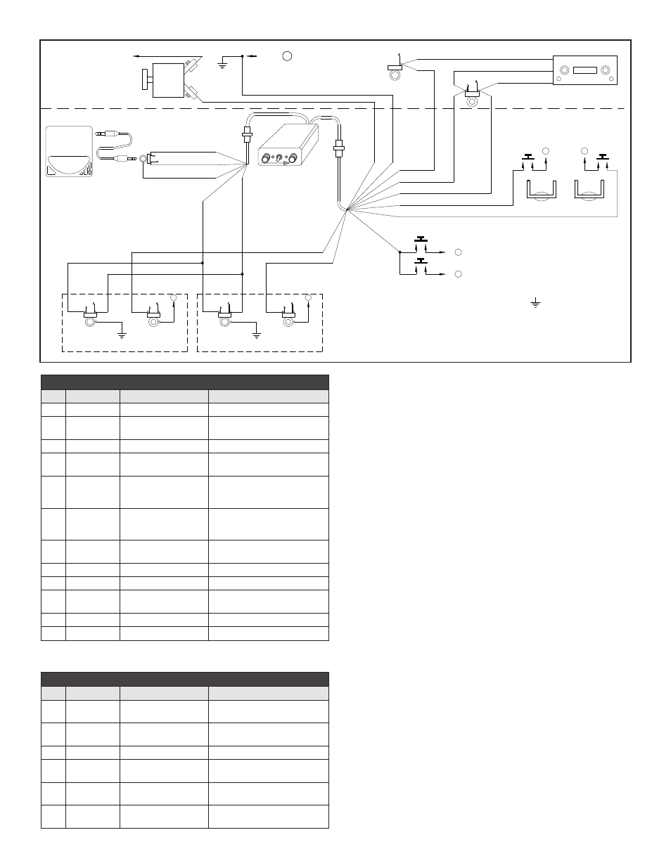
Figure 4
����� ��� � ������������ �������
�������
������
������
��������
���������
����
�����
����������������� ��������� ����
���������
��������
�������
�������
�� ����
��� �����
��������� �����
���
���
����
��������
���� ���
����
����� ��� ���
�������� �����
�����
�������� ������� �������
�� ��� �������� ���� ���
����� �� ���� �� ������������
��� ��������� �� ��� ���������
���
�����
��� �� ����� ��� �� �� ���������
���� �� ������
��
��
��
��
�� ��� ���������
�� ��� �����������
�� ���� ������������
�� ��� ����
�� ��� �����
�� ���� ����������
�� ��� �����
��
��
��
��
�
�
��
��
��
��
��
��
��
��
��
��
��
��
�
��
��
�
��
��
�����
��� ���
��������
��� ���
��
��
���������
����
������
���
����
��� ����
��
������
���
������
���������
����
���
��� ����
����
������
���
��
��������
�����
����
����
������������ ���������
�� ��������
����� ����
����� ���
Sport 200 S
INTERCOM
I N T E R C O M
Sport 200S
SQ
ON
VOL
�
�
�
�
�
��
���
� ���
���
��
��
�������� ���������������� ��������
� � ��� ������� �
�
�
�������� ������
�� ��� �����������
�� ��� �����
�� ��� ������������
�����
����� ����
���������
������
���
����
page 3
both the WHITE/GREEN and GREEN on to the TIP of the headphone
jack.
6. The Violet wire (J1 pin 12) is provided on the Sport 200 S for an optional
Push-to-intercom function. For wiring and additional instructions see
the “Sport 200 S PUSH-TO-INTERCOM INSTRUCTIONS” section on
page 4. Make sure any unused wires are properly insulated and kept
from shorting to any other wires or aircraft ground. Skip down to
the “INSTALLATION CHECK OUT AND ADJUSTMENT” section on this
page.
INSTALLATION CHECK-OUT AND ADJUSTMENTS
After the unit is installed, again check that the Sport 200 S unit chassis,
jacks, and wiring harness are clear of all aircraft operating controls and
cause no interference with them. Next, to check out the Sport 200 S
unit installation, plug in all the headset mic and phone plugs into the
respective intercom jacks. Put on the pilot’s headset and position the
boom mic close to the mouth. Voice clarity is best when the mic is at
one side of the mouth and 1/4” from the lips.
To assure that the aircraft radios, pilot’s headset, and PTT switch are
connected and functioning properly, switch the Sport 200 S ON/OFF
switch to the “off” position. If applicable, set the aircraft audio panel to
“Headphone” position. Then turn on the aircraft radio(s) as usual, and
verify that the pilot can hear the radios and can transmit using his push-
to-transmit switch and headset. Aircraft radio(s) and audio panel should
operate exactly as they did before the Sport 200 S system was installed.
Aircraft radio reception should also be heard in the co-pilot headset.
There should be no intercom between headsets with the Sport 200 S
unit “off”. Next turn the Sport 200 S unit “on”. Set the Sport 200 S volume
control to mid-position. Set Sport 200 S squelch control fully clockwise.
Verify that the Pilot and co-pilot can operate the aircraft radio(s). As
before, both headsets on the intercom will hear the aircraft radio(s).
Check that both headset positions can intercom.
It may be necessary at this time to adjust the Sport 200 S unit mic output
to the aircraft radios. A small adjustable potentiometer is provided inside
the unit for this purpose. It is accessible through a hole in the side of the
Sport 200 S chassis. It is marked “Mod. Adj.”, and can be adjusted with a
TABLE 1 - P1/J1 - See Wiring Instructions
PIN
WIRE COLOR
FUNCTION
CONNECT TO
1
White/Black
Pilot Mic Input
Ring Terminal of Pilot Mic Jack
2
White/Red
Pilot Transmit Switch
Input
Pilot Transmit Switch (PTT) (Switch
to Ground to Transmit)
3
Blue
*1 Radio Headphone Input
Radio Headphone Output
4
Black
*2
Intercom Central
Grounding Point “A”
Aircraft Chassis Ground
5
White
Radio Transmit Key
Output
Tip Terminal of Aircraft Hand Mic
Jack, or Key Input of Aircraft Radio
or Audio Panel
6
Brown
Transmit Mic Audio
Output
Ring Terminal of Aircraft Hand Mic
Jack or Mic Input of Aircraft Radio
or Audio Panel
7
Red
*3
12 through 28 VDC Power
Input
Intercom Circuit Breaker
8
NC
None
No Connection
9
NC
None
No Connection
10
White/Blue
Co-Pilot Transmit Switch
Input
Co-Pilot Transmit Switch (PTT)
(Switch to Ground to Transmit)
11
White/Orange
Co-Pilot Mic Input
Ring Terminal of Co-Pilot Mic Jack
12
Violet
*6 ICS PTT
ICS PTT Switches
TABLE 2 - P2/J2 - See Wiring Instructions
PIN
WIRE COLOR
FUNCTION
CONNECT TO
1
Green
*5
Intercom Right
Headphone Output
Tip Terminal of Headphone Jack
2
White/Green
*5
Intercom Left Head-
phone Output
Ring Terminal of Headphone Jack
3
NC
None
No Connection
4
White/Brown
*4
Music Input Left Channel
Left Music Source Headphone or
Line output
5
Black
*4
Music Input Common
Music Source Common Headphone
or Line Output
6
White/Violet
*4
Music Input Right
Channel
Right Music Source Headphone or
Line Output