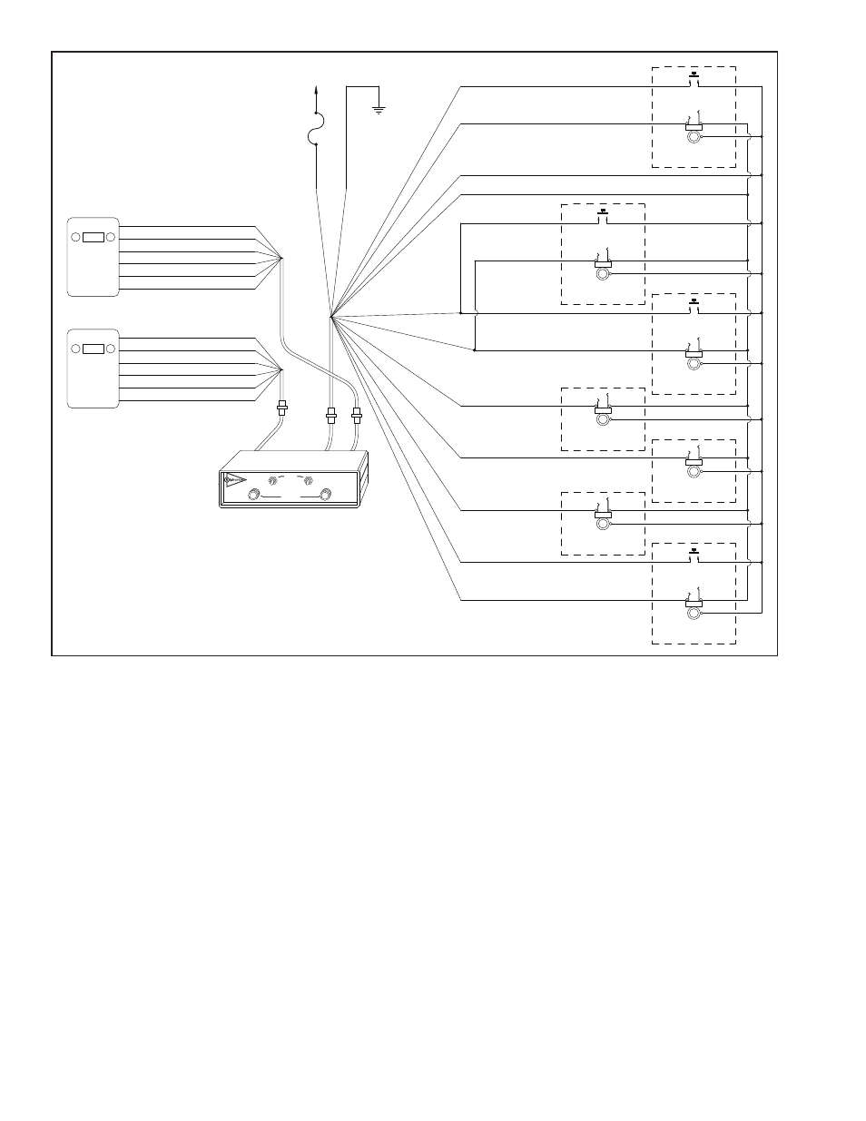
Figure 5, Us-45d/67d (dual radio) wiring diagram – Sigtronics US-DR User Manual
Page 6
fere or restrict the tilting operation. Also, make sure that the
tilting operation will not cut or sever the wiring.
Make sure that the wiring does not rest on sharp edges. Over
time the vehicle’s vibration may cause a sharp edge to cut
into the wire. Use the provided wire grommets wherever
the four conductor wire goes through the hole into a jack
box. Use wire ties or tie wraps to secure and strain relieve
the wire.
At this time do not put the covers on the jack boxes or tighten
up the PTT switches. You will need to verify the correct opera-
tion of the system before you close everything up.
Power Connections:
The UltraSound unit will run on 11-16 VDC. CAUTION:
UltraSound units are designed for negative ground vehicles
only. They can be used on positive ground vehicles only if
a Sigtronics Positive Ground Adapter is used. Contact your
Sigtronics dealer on pricing and availability.
Make sure that the vehicle power is turned off before con-
necting the UltraSound power wire. The power for the
UltraSound unit comes in on the red and green wires on the
Headset Jack and PTT Switch Cable.
Connect the red wire to vehicle power. (Try not to use a power
buss that also runs electrical motors such as fans or light bars
with rotating lights.) Connect the green wire to the vehicle
chassis ground.
Intercom Wiring Check Out
System Setup:
Before you connect the vehicle’s radios, check out the system
operation. Do the following without the vehicle’s engine run-
ning:
First plug all headsets into the respective headset jacks. Put
on one of the headsets and position the boom mic close to
the mouth, as is the practice with hand-held microphones.
Voice clarity is best when the mic is about 1/4 inch away and
slightly off center from the lips. Turn the volume control on
the headset, all the way up (clockwise).
On the UltraSound unit, set both the intercom VOLUME con-
trol and SQUELCH control to full clockwise position.
Now turn vehicle power on. Verify that you can now hear
yourself in your headset. Verify also that you can hear all the
other headsets and that they can hear you. If everything is
6
VOLUME
SQUELCH
R
TALK
LISTEN
RADIO 1
RADIO 2
AUTO
BOTH
UltraSound
RADIO
INTERCOM
PTT SWITCH
TIP
BARREL
RING
HEADSET JACK
OFFICER
PTT SWITCH
TIP
BARREL
RING
HEADSET JACK
DRIVER
PTT SWITCH
TIP
BARREL
RING
HEADSET JACK
PUMP PANEL
PTT SWITCH
TIP
BARREL
RING
HEADSET JACK
CREW #4
NOTE 3
TIP
BARREL
RING
HEADSET JACK
CREW #3
NOTE 3
TIP
BARREL
RING
HEADSET JACK
CREW #1
TIP
BARREL
RING
HEADSET JACK
CREW #2
FIGURE 5
123.00
RADIO 1
(J1-7) RED
(J1-12) GREEN
(J1-2) WHITE / RED
(J1-1) WHITE / BLACK
(J1-10) WHITE / BLUE
(J1-11) WHITE / ORANGE
(J1-9) TAN
(J1-3) BLUE
(J1-8) TAN
(J1-4) BLACK
(J1-11) WHITE / ORANGE
(J1-10) WHITE / BLUE
(J1-13) TAN
NOTE 3
(J1-14) WHITE / BROWN
NOTE 3
(J1-15) YELLOW
NOTE 3
P1
J1
P3
J3
J2
P2
SPEAKER HI
(J2-2) VIOLET
NOTE 1
SPEAKER LO
(J2-3) VIOLET
NOTE 1
PTT HI
(J2-5) WHITE
NOTE 2
MIC LO
(J2-4) BLACK
MIC HI
(J2-1) BROWN
PTT LO
(J2-6) WHITE
NOTE 2
123.00
RADIO 2
SPEAKER HI
(J3-2) VIOLET
NOTE 1
SPEAKER LO
(J3-3) VIOLET
NOTE 1
PTT HI
(J3-5) WHITE
NOTE 2
MIC LO
(J3-4) BLACK
MIC HI
(J3-1) BROWN
PTT LO
(J3-6) WHITE
NOTE 2
+11 to +16
VOLTS DC
FUSE
(1 AMP)
CHASSIS
GROUND
US-45D/67D (DUAL RADIO) WIRING DIAGRAM
NOTES:
1) CONNECT EITHER VIOLET WIRE TO THE RADIO SPEAKER HI OUTPUT.
CONNECT THE REMAINING VIOLET WIRE TO SPEAKER LO.
2) CONNECT EITHER WHITE WIRE TO THE RADIO PUSH-TO-TALK (PTT) KEY LINE INPUT.
CONNECT THE REMAINING WHITE WIRE TO THE PTT KEY LINE RETURN (PTT LO).
3) USED ON US-67D UNITS ONLY.
INTERCOM UNIT