Figure 4, Us-45s/67s (single radio) wiring diagram – Sigtronics US-DR User Manual
Page 5
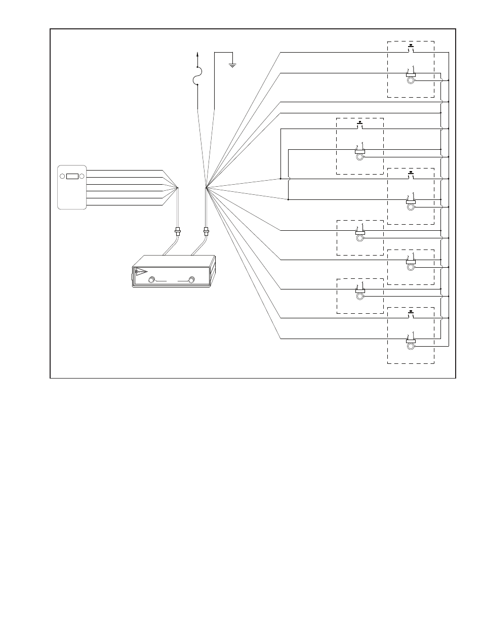
wired to the four conductor Hook-up Wire (gray) and then
the Hook-up wire connects to the jacks and the PTT switches.
For the US-45S and US-45D models, this cable has a 12 pin
connector with 10 wires. For the US-67S and US-67D, there is
a 15 pin connector and 13 wires. Before going on, plug in J1
of the cable into P1 on the Intercom unit.
Flexible four conductor hook-up wire is provided with each
system to connect each headset jack and PTT switch to the
UltraSound unit’s Headset Jack and PTT Switch Cable. Enough
wire is provided for a typical vehicle installation. If required,
additional hook-up wire can be purchased through your
Sigtronics dealer.
Each headset jack requires three wires. Each PTT switch
requires two. If an Officer’s PTT switch and headset jack are
mounted near each other, only four wires are needed.
Refer to the UltraSound Wiring Diagram (for US-45S or US-67S
see Figure 4 above for US-45D or US-67D see Figure 5 on page
6) for the exact wiring information.
The connections between the Headset Jack and PTT Switch
Cable and the hook-up wire should be soldered and insulated
for reliability. Do not use crimp type splices. They can become
intermittent over time. Use a good quality electrical tape, or
better yet, use heat shrink tubing to cover the soldered
connections. The connections to the headset jacks and PTT
switches will also have to be soldered. See Figure 3 on page
4 for jack terminal identification.
We also do not recommend using screw type terminal strips
for intercom connections. There have been several instances
where terminal strips introduced high levels of electrical
noise like alternator whine into the intercom system. It is
acceptable however to tie the intercom red and green power
wires to existing vehicle terminal strips.
The best place to run the wiring between the unit and the
jack and PTT switches is out of sight. It should be run behind
vehicle panels and/or up in the headliner. This will reduce the
chance of personnel or equipment catching on or damag-
ing the wiring. Wire routing should take into account normal
vehicle operations. Wires should not interfere with any of the
vehicle’s controls, compartments, or doors. If the vehicle’s cab
tilts up for engine servicing, run wiring along the existing
vehicle wiring bundle. Make sure that wiring does not inter-
5
INTERCOM UNIT
VOLUME
SQUELCH
R
UltraSound
INTERCOM
PTT SWITCH
TIP
BARREL
RING
HEADSET JACK
OFFICER
PTT SWITCH
TIP
BARREL
RING
HEADSET JACK
DRIVER
PTT SWITCH
TIP
BARREL
RING
HEADSET JACK
PUMP PANEL
PTT SWITCH
TIP
BARREL
RING
HEADSET JACK
CREW #4
NOTE 3
TIP
BARREL
RING
HEADSET JACK
CREW #3
NOTE 3
TIP
BARREL
RING
HEADSET JACK
CREW #1
TIP
BARREL
RING
HEADSET JACK
CREW #2
FIGURE 4
123.00
RADIO 1
(J1-7) RED
(J1-12) GREEN
(J1-2) WHITE / RED
(J1-1) WHITE / BLACK
(J1-10) WHITE / BLUE
(J1-11) WHITE / ORANGE
(J1-9) TAN
(J1-3) BLUE
(J1-8) TAN
(J1-4) BLACK
(J1-11) WHITE / ORANGE
(J1-10) WHITE / BLUE
(J1-13) TAN
NOTE 3
(J1-14) WHITE / BROWN
NOTE 3
(J1-15) YELLOW
NOTE 3
P1
J1
J2
P2
SPEAKER HI
(J2-2) VIOLET
NOTE 1
SPEAKER LO
(J2-3) VIOLET
NOTE 1
PTT HI
(J2-5) WHITE
NOTE 2
MIC LO
(J2-4) BLACK
MIC HI
(J2-1) BROWN
PTT LO
(J2-6) WHITE
NOTE 2
+11 to +16
VOLTS DC
FUSE
(1 AMP)
CHASSIS
GROUND
US-45S/67S (SINGLE RADIO) WIRING DIAGRAM
NOTES:
1) CONNECT EITHER VIOLET WIRE TO THE RADIO SPEAKER HI OUTPUT.
CONNECT THE REMAINING VIOLET WIRE TO SPEAKER LO.
2) CONNECT EITHER WHITE WIRE TO THE RADIO PUSH-TO-TALK (PTT) KEY LINE INPUT.
CONNECT THE REMAINING WHITE WIRE TO THE PTT KEY LINE RETURN (PTT LO).
3) USED ON US-67S UNITS ONLY.