Upgrading a spa installation to a sci-s, Page 4 – Sigtronics SCI-S6 Installation Instructions User Manual
Page 4
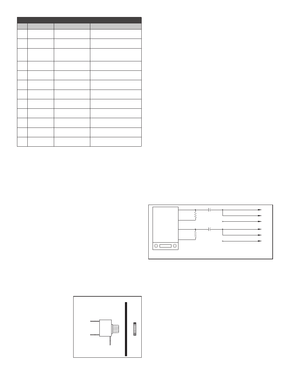
TABLE 2 - J2/P2 - See Wiring Instructions
PIN
WIRE COLOR
FUNCTION
CONNECT TO
1
Green *7
Pilot Intercom Right
Headphone Output
Tip Terminal of Pilot Headphone Jack
2
Grey *7
Co-Pilot Intercom Right
Headphone Output
Tip Terminal of Co-Pilot Headphone
Jack
3
Yellow *7
Passenger Intercom
Right Headphone
Output
Tip Terminal of Passenger
Headphone Jacks
4
Orange *6
Crew Music Input
Left Channel
Left Crew Music Source
Hdph/Line Output
5
Black *6
Crew Music Input
Common
Crew Music Source
Common Hdph/Line Output
6
Violet *6
Crew Music Input
Right Channel
Right Crew Music Source Hdph/Line
output
7
White/Green *7
Pilot Intercom Left
Headphone Output
Ring Terminal of Pilot Headphone
Jack
8
White/Grey *7
Co-Pilot Intercom Left
Headphone Output
Ring Terminal of Co-Pilot Headphone
Jack
9
White/Yellow *7
Passenger Intercom
Left Headphone Output
Ring Terminal of Passenger
Headphone Jacks
10
White/Brown *6
Passenger Music Input
Left Channel
Left Passenger Music Source Hdph/
Line output
11
Black *6
Passenger Music Input
Common
Passenger Music Source Hdph/Line
Common Output
12
White/Violet *6
Passenger Music Input
Right Channel
Right Passenger Music Source
Hdph/Line Output
1. The blue wire from Pin 3 must be connected to the aircraft radio
headphone output - NOT the speaker output.
2. Connect all intercom mic jack grounds to a single aircraft chas-
sis ground point - Point “A” - as shown in Figure 4. (Use the
black washers supplied to insulate the intercom mic jacks from
aircraft chassis ground). Note this intercom central grounding
point is used to eliminate any unwanted electrical noises, such
as alternator whine or strobe noise, from being induced into the
intercom system through the grounds. All intercom mic jack bar-
rels must be insulated from ground where they are mounted and
connected back to Point “A” on their own individual ground wire.
Similarly, both intercom ground wires (J1 pin 4) and the push-to-
transmit switch grounds must also be connected back to Point
“A”. It is not necessary, however, to connect the headphone jack
barrels to Point “A”. They can either be grounded where they are
mounted or some place nearby.
3. The red wire may be connected to either 12V (14V) or 24V (28V)
power source. No switching or adjustments are required to op-
erate from either source.
4. Tan wires (J1 pins 8, 9, 13, 14) are only used on installations that
require extra intercom positions.
5. Tan wires pins 13 and 14 are provided on SCI-S6 units only.
6. The SCI-S system provides two separate music inputs - one
for the crew and the other for the passengers. These music
inputs accept Headphone
(Walkman) or Line level
music sources. The wir-
ing diagram shows how
to wire the SCI-S for dual
music inputs for use with
portable stereo music
sources. Two small stereo
input jacks are supplied
for this purpose. Connect
the Orange, Violet, and
Black wires to one jack
as shown in Figure 4. Identify the jack terminals using Figure 5.
Connect the White/Brown, White/Violet, and Black wires to the
second jack. Drill a 1/4-inch hole for each jack and mount on the
aircraft panel. To use, connect an adapter cable between the
music input jack and the output of the portable stereo. Suitable
cables are available at your local Stereo or electronics store as
well as from Sigtronics.
If only a single portable music source is to be used there are
two different methods this can be done. The first way and most
flexible is to wire just like the wiring drawing and use a mini-jack
“Y” or splitter (also available at your local Stereo or electronics
store) and dual cables to go from one stereo into both crew and
passenger input jacks. The second way is to use just one of the
supplied music input jacks and connect both inputs to it. Do this
by connecting both the Orange and the White/Brown wire to the
TIP terminal, the Violet and White/Violet to the RING, and both
Blacks to the BARREL.
Speaker level output car stereo music sources can also be used
with the SCI-S system. A Floating Ground Adapter or a four wire
to three wire converter will have to be used between the Stereo
and the SCI-S music inputs. Figure 6 shows such an adapter
and how it is wired into the SCI-S.
7. The Sigtronics SCI-S system can be installed as shown for use
with Stereo headsets. Alternatively, monaural general aviation
type headsets can be used. To use monaural headsets follow
the installation instructions as normal except for the wiring of
the stereo headphone jacks. Use the stereo headphone jacks
supplied with the Sigtronics SCI-S but leave the “RING” con-
nections open. Instead connect both headphone wires to the
“TIP” of the respective jacks. Connect both the WHITE/GREEN
and GREEN on to the TIP of the pilot jack, WHITE/GREY and
GREY on the copilot’s and WHITE/YELLOW and YELLOW on
the passengers.
8. Make sure any unused wires are properly insulated and kept
from shorting to any other wires or aircraft ground. Skip down to
the “INSTALLATION CHECK OUT AND ADJUSTMENT” section
on page 5.
UPGRADING A SPA INSTALLATION TO A SCI-S
Chassis Mounting
The SCI-S4 is specifically designed to easily replace a SPA-400.
Similarly, the SCI-S6 can replace a SPA-600. The panels are ex-
actly the same dimensions (1” x 2.5”), however the SCI-S units are
1 3/4” longer than the SPA units. You will have to make sure that
you have the extra depth required behind your panel. Five mount-
ing holes are exactly in the same positions. The center hole will
have to be enlarged from 1/4” to 7/16”, the two outer holes will have
to be enlarged to 9/16”, and two additional holes drilled to 3/16” (As
per template).
������
���
����
��������
������
�������
�������� �����
���
������ �
�
�����
����
������
�
�
�
�
�
�
�
�
�
�
� � ��� ���� � ���� ��������
� � ��� ���� �� ���� ���������
�� ����������
�� ����������
�� ��������
�� ��� ������
�� ��� ������
�� ��� �����
�� ���� ������������
�� ���� �����������
�� ���� �����
������ �
�
page 4