Chassis installation – Sigtronics SCI-S6 Installation Instructions User Manual
Page 2
OPTION “A” - FULL MUSIC MUTE DURING ICS - When listening
to music and someone speaks on the intercom the default fac-
tory operation is to partially mute the music so you can hear the
conversation. If you prefer however, the music can be completely
muted during intercom if you enable this option. Note - during radio
transmission and reception, the music will always be fully muted
regardless if this option is selected or not. This is for communica-
tion safety reasons.
OPTION “B” - PILOT TRANSMIT PRIORITY - If the pilot and the
copilot key at the same time (not a common occurrence) the default
operation is that both microphones will go out the aircraft radio to
the tower. If you prefer only the pilot’s microphone active when both
press their PTT’s simultaneously then enable this option. Note - if
only one of the pilots
presses his PTT only
his mic will go out over
the radio regardless if
this option is selected
or not.
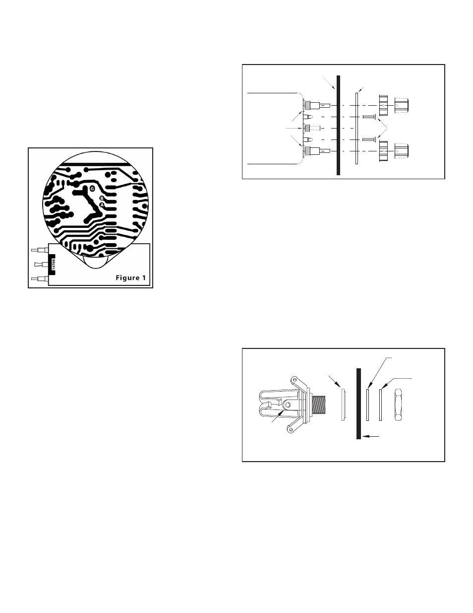
To enable either or
both of these options,
remove the four screws
on the bottom of the
SCI-S unit and remove
the cover. Refer to
Figure 1. To enable op-
tion A (full music mute
during ICS), solder a
small jumper from the
pad labeled “A” to the
pad labeled “G”. To enable option B (pilot transmit priority) solder
a small jumper between pad “B” and pad “G”. Replace the cover
and the four screws and tighten. Removing these jumpers will de-
activate the options.
CHASSIS INSTALLATION
To upgrade an existing SPA-400 installation to an SCI-S4 or a SPA-
600 to an SCI-S6 skip to the “UPGRADING A SPA INSTALLATION
TO A SCI-S” section on page 4. For a completely new intercom
installation, continue below.
UNIT PLACEMENT
The SCI-S unit has been designed to mount either horizontally or
vertically in your aircraft panel. The location selected for the SCI-
S unit requires a minimum front panel area of 2 1/2” by 1”. Depth
required behind panel is 6” plus cable access.
CAUTION: Move the aircraft flight controls through the limits of
travel while observing the selected area and making sure that the
rear of the intercom and cable will not interfere with any aircraft
control components.
PANEL PREPARATION:
1. Position the adhesive drill template on the aircraft panel in the
selected area.
2. Center punch each hole at the cross lines. (Five holes are in
a straight line and equally spaced 0.4” apart. The two Squelch
Indicator Light holes are 0.8” apart).
3. Drill 1/8” pilot holes in all seven places.
4. Enlarge two holes to 9/16”, one hole to 7/16”, and two holes to
3/16” per the template.
MOUNTING CHASSIS (See Figure 2)
1. Remove the knobs from the Volume and Squelch controls using
a 0.050” Allen wrench. NOTE: DO NOT REMOVE the nuts from
the Volume/Squelch, or ALL/ISO/CREW controls.
2. Insert the SCI-S unit from the rear of the aircraft panel with the
appropriate arrow on the unit chassis pointing upwards. Make
sure the squelch indicator lights have unrestricted movement
through aircraft panel.
3. Install the printed SCI-S panel and lightly thread the two 4-40
screws through the holes in intercom panel. The nuts on the
Volume/Squelch and ALL/ISO/CREW controls will fit inside the
9/16” and 7/16” diameter holes.
4. Tighten the two screws.
5. Install the knobs on the Volume (VOL) and Squelch (SQ) control
shafts and tighten the Allen screws.
MOUNTING HEADPHONE AND MICROPHONE JACKS (See
Figure 3)
1. Locate the mounting areas. (One mic and one headphone jack
required for each headset). Again, make sure that the jacks will
not interfere with any aircraft control components. (Note that the
jack contacts will expand when a plug is inserted into the jack.)
2. Drill 3/8” diameter holes for headphone jacks and install.
3. Drill 1/2” diameter holes for the mic jacks and install with the
insulating washers supplied. (See Figure 3)
��������
������
����
���������
������
����
�����
������
���
��������
�����
����
������
���
Figure 3
Microphone Jack
�� ��� ������
����� ����
��������
�����
��������
�����
����
���� ������
����
���
��������
������ �
page 2