Spa-600n installation drawing figure 4, Intercom spa-600 – Sigtronics SPA-600N User Manual
Page 2
MOUNTING CHASSIS (continued)
5. Install panel and lightly thread nut on to ON-OFF switch. Nuts and
washers on Volume and Squelch controls should fit inside the 3/8”
diameter holes.
6. Select two 4-40 screws through holes in intercom panel. Tighten ON-
OFF switch nut.
7. Install knobs on Volume (VOL) and Squelch (SQ) control shafts using
.050” Allen wrench.
MOUNTING HEADPHONE AND MICROPHONE JACKS:
1. Select mounting areas. (One mic and one headphone jack for each
headset). Again, make sure the jacks will not interfere with aircraft
control components.
2. Drill 3/8” diameter holes for headphone jacks and install.
3. Drill 1/2” diameter holes for mic jacks and install with insulating
washers supplied. (See Figure 3).
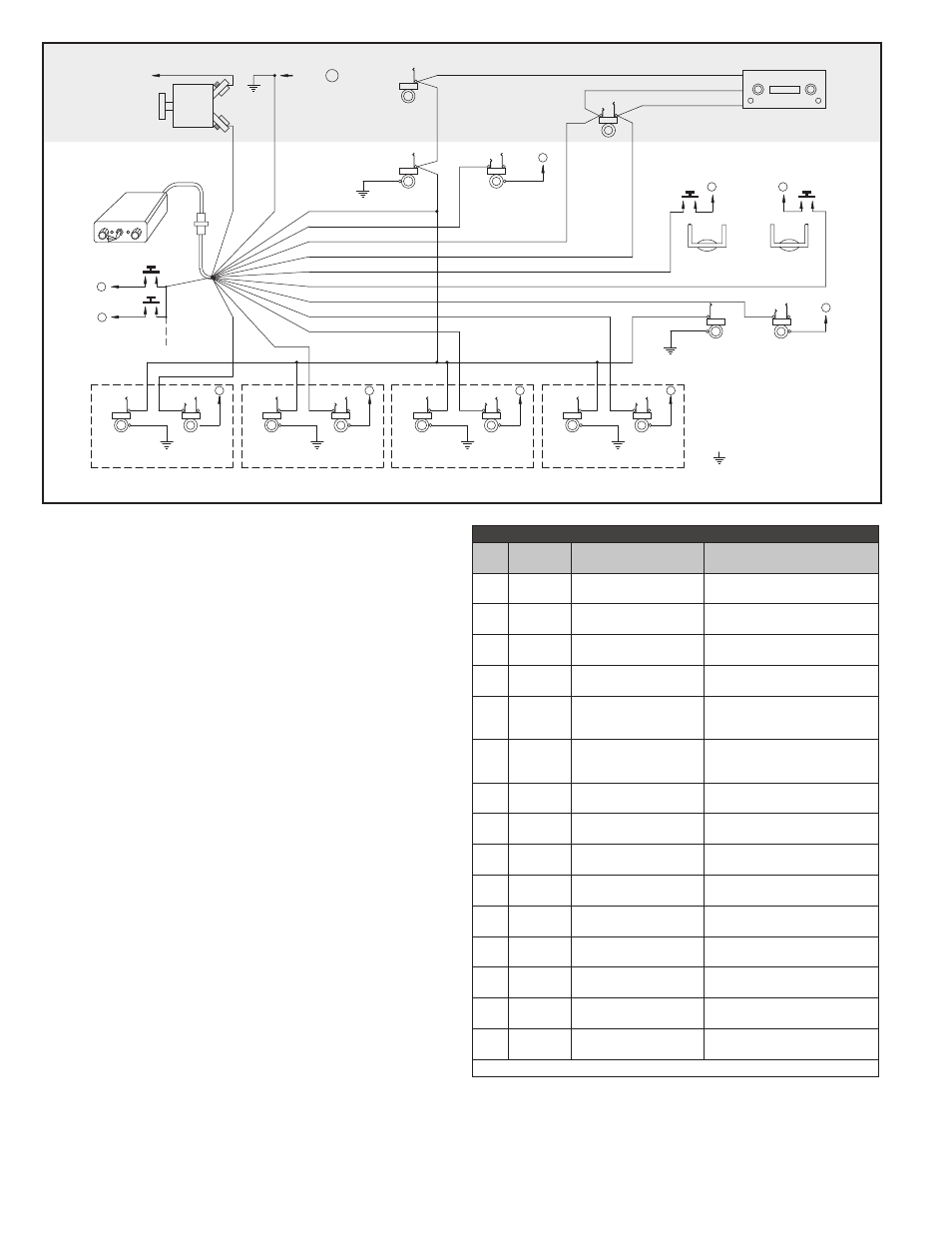
WIRING INSTRUCTIONS
Connections should be made as shown in Figure 4 and indicated in Table 1
*A. White / red (pilot push-to-talk) must correspond with white / black (pilot
mic input) as shown.
*B. The blue wire from Pin 3 must be connected to the aircraft radio
headphone output- NOT the speaker output.
*C. Connect all intercom mic jack grounds to Point A as shown in Figure
4. (Use black washers supplied to insulate intercom mic jacks from
aircraft chassis ground).
*D. Do NOT connect transmit switches to white (key) wire.
*E. Red wire may be connected to either 12 (14V) or 24 (28V) power
source. No switching or adjustments are required to operate from
either source.
*F. Tan wires from Pins 8 and 9 are only used on 4-way installations.
FINAL CHECKOUT AND ADJUSTMENT
After the unit is installed, again check that the intercom chassis, jacks,
and wiring harness are clear of all aircraft operating controls and cause
no interference with them. Check out the intercom functions by following
the Operating Instructions.
It may be necessary at this time to adjust the intercom mic output to
the aircraft radios. A small, square, adjustable trimmer potentiometer is
provided inside the unit for this purpose. It is accessible through a hole
in the side of the case, marked “Mod. Adj.”, and can be adjusted with a
screwdriver. In the event of over modulation (garbled) or reports of weak
transmissions over the aircraft radio, an appropriate adjustment can be
made. Clockwise rotation increases the output level to the aircraft radio
mic input. Counter-clockwise rotation decreases modulation level. This
adjustment sometimes needs to be made after initial installation of the
intercom or if a new radio is installed. (The output is set for unity gain at
Sigtronics.)
Weight: Intercom with panel and knobs (4.5 oz.)
Jacks and wiring harness (12.5 oz. maximum)
Current Draw: 0.07 amps @ 28 volts
FAA TSO: C50b ENV. CAT (DO-160) CFBBBX
INTERCOM
SPA-600
SQ
ON
VOL
SPA-600N
INTERCOM
CO-PILOT
HEADPHONE JACK
CO-PILOT
MIC JACK
PILOT
HEADPHONE JACK
AIRCRAFT
HEADPHONE
JACK
AIRCRAFT
HAND MIC
JACK
PILOT
MIC JACK
BARREL
BARREL
TIP
TIP
TIP
TIP
RING
RING
AIRCRAFT RADIO
12345
AIRCRAFT / INTERCOM INTERFACE AREA
PILOT
PTT SWITCH
CO-PILOT
PTT SWITCH
TO AIRCRAFT
POWER BUSS
12 / 28 VDC
PUSH-TO-INTERCOM
SWITCHES
(1 PER HEADSET)
POINT
( INTERCOM
CENTRAL
GROUND
POINT )
(3) BLUE
BLUE
(1) WHITE / BLACK
(6) BROWN
(5) WHITE
(8) TAN
(9) TAN
(13) TAN
(1
4)
TA
N
(1
2)
VIO
LE
T
(2) WHITE / RED
(10) WHITE / BLUE
(11) WHITE / ORANGE
(7
)R
E
D
(4
)B
LA
C
K
P1
J1
HEADPHONE AUDIO
MIC AUDIO
RADIO MIC KEY
TO
A
TO
A
HEADPHONE
JACK
MIC
JACK
BARREL
BARREL
TIP
TIP
RING
PASSENGER 4
TO
A
HEADPHONE
JACK
MIC
JACK
BARREL
BARREL
TIP
TIP
RING
PASSENGER 3
TO
A
HEADPHONE
JACK
MIC
JACK
BARREL
BARREL
TIP
TIP
RING
PASSENGER 2
TO
A
HEADPHONE
JACK
MIC
JACK
BARREL
BARREL
TIP
TIP
RING
PASSENGER 1
TO
A
BARREL
TIP
RING
TO
A
TO
A
TO
A
TO
A
A
BARREL
TIP
���
�������� ������� �������
��� �� ����� ��� �� �� ���������
�� ��� �������� ���� ��� �����
�� ���� �� ������������ ���
��������� �� ��� ���������
�����
���� �� ������
INTERCOM
CIRCUIT
BREAKER
( 1 AMP )
Table 1
Plug
Pin #
Wire Color
Function
Connect To:
1
White /
Black
Pilot Mic Input
Ring Terminal of Pilot Intercom
Mic Input Jack
2
White /
Red *A
Pilot Transmit Switch
Input
Pilot Transmit Switch (PTT)
(Switch to Ground to Transmit)
3
Blue *B
Headphone - Radio and
Intercom Outputs
Radio Headphone Output and all
Headphone Jacks
4
Black *C
Ground
Hand Mic Jack Ground Terminal
(Point A)
5
White *D
Transmit Relay (Key)
Control Output
Tip Terminal of Aircraft Mic Jack
or Key Input of Aircraft Radio or
Audio Panel
6
Brown
Mic Audio Output
Ring Terminal of Aircraft Mic Jack
or Input of Aircraft Radio
or Audio Panel
7
Red *E
12 VDC through 24 VDC
Power Input
Intercom Circuit Breaker
8
Tan
Passenger #1 Mic Input
Ring Terminal of Passenger #1
Mic Jack
9
Tan
Passenger #2 Mic Input
Ring Terminal of Passenger #2
Mic Jack
10
White /
Blue
Copilot Transmit Switch
Copilot Transmit Switch (PTT)
11
White /
Orange
Copilot Mic Input
Ring Terminal of Intercom Copilot
Mic Input Jack
12
Violet
Push to Intercom Input
Push to Intercom Switches
13
Tan
Passenger #3 Mic Input
Ring Terminal of Passenger #3
Mic Jack
14
Tan
Passenger #4 Mic Input
Ring Terminal of Passenger #4
Mic Jack
15
No Connection
* See Wiring Instructions
SPA-600N Installation Drawing
Figure 4
spa-600n.pdf 1-8-2007 Form SPA-600N-IS REV B