Sigtronics SPA-600N User Manual
Spa-600n installation and operating instructions, For very high noise applications)
The Sigtronics’ SPA-600N is a voice actuated intercom with “transmit
through the aircraft radio capability” using your push-to-talk switch. Three
controls are provided:
Power Switch — Turns unit on and off.
Volume Control — Controls the intercom volume.
Squelch Control — Allows the setting of voice actuated (VOX) operation
of the intercom for variations in background noise levels and differences
in headset microphones.
OPERATING INSTRUCTIONS
I. INTERCOM MODE
A. Put on headset/s and position the boom mic close to the mouth, as
is the practice with a hand-held mic. Voice clarity is best when mic
is at one side of the mouth and 1/4” from the lips.
B. Set audio panel to “Headphone” position, if applicable.
C. Turn power “on” and set Volume Control to a low level. (1/4th to 1/3rd
open for best signal to noise ratio).
D. For voice activated intercom adjust Squelch Control clockwise
until back ground noise becomes audible. Then rotate counter-
clockwise small amounts until the noise diminishes. Now make small,
incremental adjustments until voice triggers unit on. This procedure
is necessary because the squelch system is a “fast on, slow off”
circuit.) Small adjustments may be necessary if aircraft background
noise changes signifi cantly. To use the push-to-intercom feature, turn
the squelch control on the intercom fully counter-clockwise. Then to
activate, push the ICS push-to-intercom switch.
II. RADIO TRANSMIT MODE — Transmitting from both pilot and co-pilot
positions is possible on a one-at-a-time basis. The transmitting mic
disables all other mics. When you are ready to talk to ATC, depress the
transmit switch on your yoke and your voice is automatically transmitted
via the aircraft radio.
You will hear your own voice when transmitting via the aircraft radio
side-tone return, If the radio does not have side-tone, then you will not
hear your voice. A minor modifi cation to the intercom will enable it to
simulate side-tone.
III. RADIO MONITORING — Radio monitoring is automatic. The radio
monitor circuit is always active; even with intercom power switch
“off”.
IV. SOLO FLIGHTS — Since the intercom is not needed during solo fl ights,
it may be turned off. The pilot will still hear the aircraft radio, since
this circuit is always active, and the pilot may transmit to ATC via his
push-to-talk switch. (Co-pilot position cannot transmit when intercom
is off).
V. BACK-UP — If a problem is suspected in the intercom, simply turn it
off. You will still receive the aircraft radio and will be able to transmit
from the pilot’s position. The hand mic may also be used, however, the
Transcom should be turned off and you should unplug your boom mic
from the mic jack. (Leave headphone plugged in for radio reception).
CHASSIS INSTALLATION
The Sigtronics’ SPA-600N has been designed to mount either horizontally
or vertically in your aircraft panel. All necessary mounting hardware has
been supplied for a 6-way installation. (A round faceplate is also available
from Sigtronics to fi t a 2 1/4” round instrument hole).
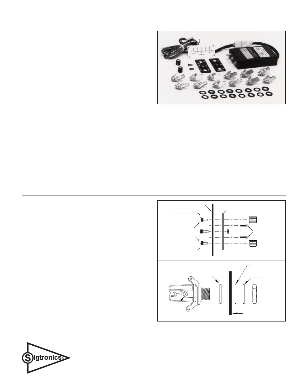
HARDWARE SUPPLIED
Six Headphone Output Jacks — Accept standard .250” aircraft headphone
plugs.
Six Microphone Input Jacks — Accept standard .206” aircraft microphone
plugs (i.e. amplifi ed dynamic or electret). (U93 plug compatible jacks can
be used in place of the jacks provided).
Mic Jack Insulating Washers: 6 fl at and 6 shoulder.
Panel: Lettered on both sides.
Control Knobs (2), Switch Nut (1), 4-40 Screws (2)
Template: Hole size pattern for drilling aircraft panel.
Aircraft / Intercom interface cable (4 feet long)
The location selected requires a minimum front panel area of 2-1/2” by
1-1/16”. Depth required behind panel is 4-3/16” plus cable access.
Caution: Move aircraft fl ight controls through limits of travel while
observing selected area to make sure rear of intercom and cable will not
interfere with aircraft control components.
PANEL PREPARATION:
1. Position adhesive template on aircraft panel in selected area.
2. Center punch each hole at cross lines. (The fi ve holes are in straight
line and equally spaced 0.4” apart.)
3. Drill 1/8” pilot hole all fi ve places.
4. Enlarge holes to 1/4” and 3/8” per template.
MOUNTING CHASSIS: See Figure 2.
1. Remove nut from Transcom ON-OFF switch bushing.
2. Remove knobs from Volume and Squelch controls. NOTE: DO NOT
REMOVE nuts from Volume and Squelch control potentiometers.
3. Remove two 4-40 panel screws and remove panel from Transcom
chassis.
4. Insert Transcom from rear of aircraft panel with appropriate arrow
pointing upwards.
(continued)
SPA-600N INSTALLATION AND OPERATING INSTRUCTIONS
(For Very High Noise Applications)
��������
�����
���� ���� ��
������
���
��������
�� ��� ������
����� ����
����
����
AIRCRAFT
PANEL
��������
������
����
���������
������
����
�����
������
���
��������
�����
����
������
���
Figure 2
Figure 3
Microphone Jack
Sigtronics Corporation
178 East Arrow Highway
San Dimas, CA 91773
Phone: (909) 305-9399
E-mail: [email protected]
Web Site: www.sigtronics.com
Figure 1