Control overview – Shellab SHC28R-2 User Manual
Page 7
7
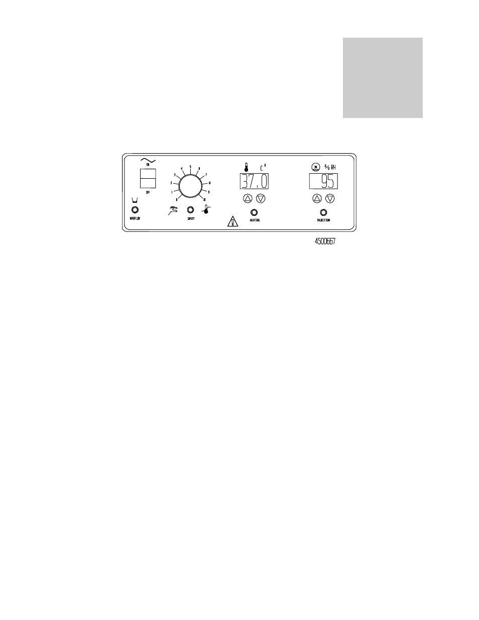
CONTROL OVERVIEW
4.1
Power Switch: The main power I/O (On/Off) switch controls all power to the unit, and must be in the
I/On position before any systems are operational.
4.2
High Limit Safety Thermostat: This control is marked SAFETY and is adjacent to the power switch.
It is completely independent of the Main Temperature Controller and guards against any failure which
would allow the temperature to rise past set point. If the temperature rises to the safety set point, the
Safety takes control of the heating element and allows continued use of the unit until the problem can
be resolved or service can be arranged. Please note that it is not recommended that the unit be
allowed to operate using only the Safety Thermostat as temperature uniformity will suffer.
4.3
High Limit Indicator: This pilot light, located on the Main Control Panel just above the word
SAFETY, comes ON when the High Limit Safety Thermostat is activated. Under normal operating
conditions this pilot light should never come on.
4.4
Main Temperature Controller: This control is marked C
and consists of the digital display and
UP/DOWN arrow pads for inputting set point temperatures and calibration.
4.5
Heating Indicator: This pilot light is marked HEATING and is on when the heating elements have
been activated to reach and maintain set point.
4.6
Relative Humidity Controller: This control is marked % RH, and consists of the digital display and
UP/DOWN arrow pads for inputting set point percents and calibration. The Relative Humidity
Controller maintains internal humidity through a direct set point of 1% increments and the digital
display indicates in 1% increments. This control is solid state and proportional. The controller utilizes a
solid state thin film capacitive humidity sensor to sense the humidity within the chamber.
4.7
Injection Indicator: This pilot light is marked INJECTION and is on when water vapor is being
injected into the chamber from the vapor generator.
4.8
Water Low Indicator: This pilot light is marked WATER LOW and is on when the water level drops
in the vapor generator. The float switch is tripped, the vapor generator is turned off, and water is
released from the supply. When the vapor generator becomes full, the float switch is tripped again,
the vapor generator is turned on, and the WATER LOW pilot light turns off.
4.9
Chart Recorder: Adjacent to the control panel is a cover plate that can be removed if a chart
recorder is to be installed. Chart recorders are available from your dealer. For further information see
Section 7.0, Chart Recorder Installation.
Section
4