Pressure balanced shower valve – Santec PB-3600 User Manual
Page 3
0 5
FIGURE 2
Pressure Balanced Shower Valve
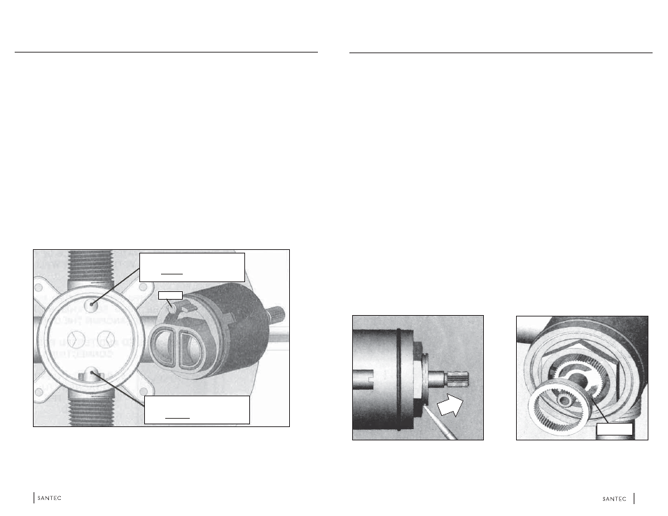
2 . R e v e r s i n g t h e C a r t r i d g e
When a valve is installed with reversed supply connections, the cartridge can be reversed to allow normal
operation (see Figure 2).
Remove the trim sleeve to expose top of valve.
Loosen and remove hex nut above cartridge.
Remove cartridge from valve cavity.
Look into cavity to see upper and lower locating holes for cartidge pin on the floor of the cavity.
Re-insert cartidge, aligning the pin with lower locating hole (partially caut away by discharge opening).
Press cartridge in firmly to assure that pin has been properly inserted.
Secure cartridge by tightly reassembling the hex nut.
Reassemble trim.
1.
2.
3.
4.
5.
6.
7.
8.
0 6
REGULAR INSTALLATION
USE UPPER LOCATING HOLE
PIN
REVERSE INSTALLATION
USE LOWER LOCATING HOLE
FIGURE 3
FIGURE 4
Pressure Balanced Shower Valve
2 . S e t t i n g H o t L i m i t : I M P O R T A N T ! !
THE REMOVAL OF THE WARNING LABEL BARRIER ON THE FACE OF THIS MIXING VALVE
CONSTITUTES THE TRANSFER OF LIABILITY FROM THE MANUFACTURER TO THE
INSTALLER UNDER THE LAWS OF THE UNITED STATES. IT IS THE INSTALLERS
RESPONSIBILITY TO SET THE MAXIMUM OUTPUT TEMPERATURE OF THE VALVE TO NO
MORE THAN 120F, IN ACCORDANCE WITH ASSE/ANSI STANDARD 1016-1996 DEALING WITH
INDIVIDUAL THERMOSTATIC, PRESSURE BALANCING AND COMBINATION PRESSURE
BALANCING AND THERMOSTATIC CONTROL VALVES FOR INDIVIDUAL FIXTURES SECTION
4.2.2., TEMPERATURE LIMIT SETTING.
TO PROPERLY SET THE LIMIT RING, YOU MUST USE A THERMOMETER OR CALIBRATED SENSING
DEVICE TO ACCURATELY MEASURE THE OUTLET WATER TEMPERATURE. THE ADJUSTMENT RING
IS POSITIONED AS FOLLOWS:
Expose the top of the cartridge by removing the trim sleeve from the valve body. Do not remove the
hex nut holding it in place.
Remove the grey adjustment ring by placing the blade of a knife into the groove and prying it off (see
Figure 3).
Note the stop on the bottom of the ring (see Figure 4). The further it is re-oriented in a counter-
clockwise direction, the shorter the travel allowed (and thus, the lower the temperature output possible).
IMPORTANT: BEFORE RE-ORIENTING THE RING, BE SURE THE STEM IS IN THE FULL OFF
POSITION.
1.
2.
3.
TAB